Home/
Registry/
Ford/
Bronco/
1992-1996/
“Eddie Bauer”/
Photo
supermotors.net/registry/media/1126510
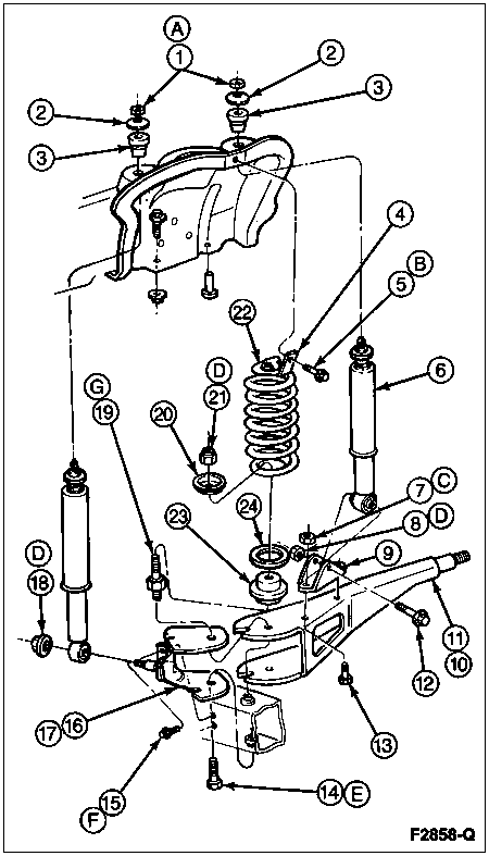
Ford Bronco Front Coil Spring & Shock Absorber Exploded Diagram (F2858-Q)
Reference · 1992-1996 BroncoAll 169 exploded parts diagrams

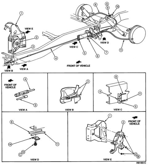












Exploded parts breakdown drawing of a front suspension assembly showing coil spring, shock absorbers, spindle, and numbered hardware.
Part of 1992-1996 Ford Bronco Exploded Parts Diagrams
This document is a black-and-white exploded parts diagram, likely from a Ford factory service manual, showing a front suspension assembly with coil spring and shock absorbers. The illustration depicts an upper spring/shock mounting area (frame bracket or crossmember) at the top, a coil spring (callout 22) with spring seat and insulator components (20, 21, 23, 24), two shock absorbers (one labeled 6), and a lower suspension arm/radius arm assembly with associated fasteners, washers, nuts, bushings, and brackets (callouts 7 through 18). Numbered callouts 1 through 24 and lettered callouts A through G identify individual parts and fastener groups, but no legend, part names, part numbers, or torque specifications are included in this scan, those would appear on an accompanying page. The only textual identifier is the Ford-style illustration reference code 'F2858-Q' in the bottom right corner. A reader can learn the assembly order and relative positions of the shock absorbers, coil spring, insulators, retainers, and mounting hardware for the front suspension, but must consult the matching legend page to know part names or numbers for each callout.
Is this accurate? Sign in to help verify it.
Frequently asked questions
- What does this diagram show?
- It is an exploded illustration of a front suspension assembly, showing shock absorbers, a coil spring (callout 22), spring seats/insulators, upper mounting hardware, and the lower suspension arm with brackets and fasteners.
- Does this diagram include part names or part numbers?
- No. It only shows numbered callouts (1-24) and lettered callouts (A-G) pointing to components. The only text is the illustration reference code F2858-Q; the legend identifying each callout is not included in this scan.
- How many callouts are on the diagram?
- There are numbered callouts 1 through 24 (some numbers like 2 and 3 appear twice) and lettered callouts A through G (with D appearing multiple times).
- What is the figure reference code on this diagram?
- The code in the bottom right corner is F2858-Q.






No comments yet.