Home/
Registry/
Ford/
Bronco/
1992-1996/
“Eddie Bauer”/
Photo
supermotors.net/registry/media/1157088
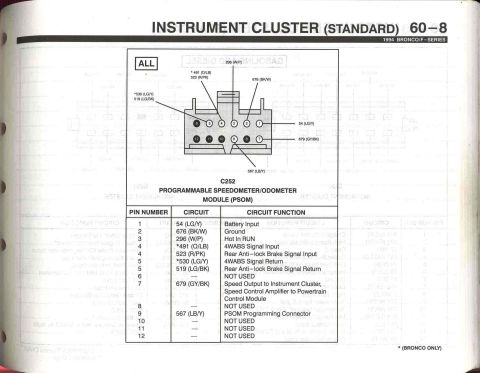
1994 Ford Bronco/F-Series Instrument Cluster PSOM Wiring Diagram - EVTM 60-7

Wiring diagram for the 1994 Bronco standard instrument cluster Programmable Speedometer/Odometer Module circuit.
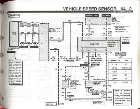
This is page 60-7 from the 1994 Ford Bronco/F-Series Electrical and Vacuum Troubleshooting Manual (EVTM), showing the wiring diagram for the standard instrument cluster's Programmable Speedometer/Odometer Module (PSOM). The PSOM receives battery power from fuse 8 (15A, hot at all times) via circuit 54 LG/Y through splice S214, and run power from fuse 18 (10A, hot in run) via circuit 296 W/P through splice S242. A test input on pin 9 (circuit 567 LB/Y through connector C252) connects to the PSOM programming enable connector via C232. The vehicle speed sensor connects via circuits 523 R/PK, 519 LG/BK, and 679 GY/BK, with Bronco-only alternate circuits 491 O/LB and 530 LG/Y. Ground is through circuit 676 BK/W to splice S216, then 570 BK/W to ground G200. A note explains that the solid-state module's microprocessor converts the ABS sensor input to a standard 8000 pulses-per-mile speed signal fed to the PCM and Speed Control Servo/Amplifier. A connector reference list maps C177 (cell 97), C268 (49), C269 (149), and C1027 (27, 28). Cross-references point to power distribution (pages 13-15, 13-17), fuse panel (13-3, 13-9, 13-13), grounds (10-10), and vehicle speed sensor (64-1, 64-2).
Is this accurate? Sign in to help verify it.
Frequently asked questions
- Which fuses power the PSOM/instrument cluster on a 1994 Bronco/F-Series?
- Fuse 8 (15A, hot at all times) supplies battery power via circuit 54 LG/Y, and fuse 18 (10A, hot in run) supplies run power via circuit 296 W/P.
- What wire colors connect the vehicle speed sensor to the PSOM?
- Circuits 523 R/PK (pin 4), 519 LG/BK (pin 5), and 679 GY/BK (pin 7). On Bronco only, alternates 491 O/LB and 530 LG/Y are used.
- How is the PSOM grounded?
- Pin 2 goes through connector C252 on circuit 676 BK/W to splice S216, then circuit 570 BK/W to ground G200. See Grounds page 10-10.
- What speed signal does the PSOM output?
- The module's integrated microprocessor receives an input from the ABS sensor and converts it to a standard 8000 pulses per mile speed signal, provided to the PCM and Speed Control Servo/Amplifier Assembly.
- Where is the PSOM programming enable connection?
- The Enable PSOM Programming Connector (cell 151-15 E1) connects via C232 on circuit 567 LB/Y through C252 to pin 9 (TEST) of the module.
Comments
More from this build






No comments yet.