Home/
Registry/
Ford/
Bronco/
1980–1986/
“That dirty old truck”/
'84-89 Fuel Reservoirs
supermotors.net/registry/2742/66025
Album section
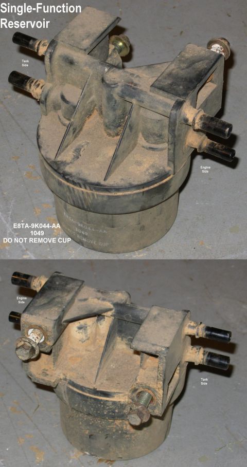
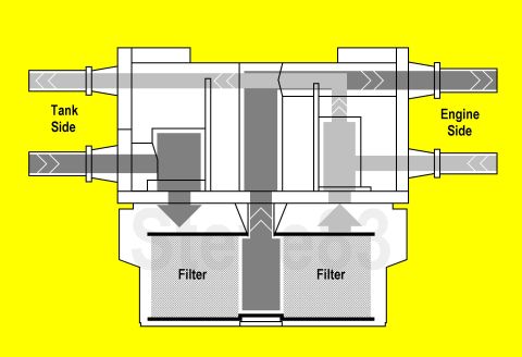
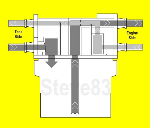
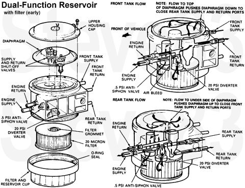
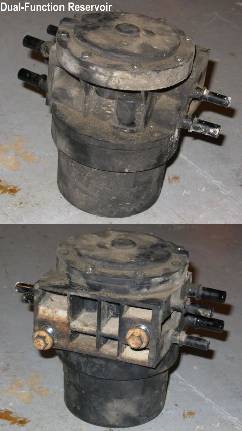
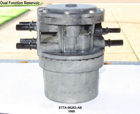
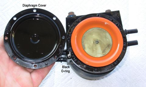
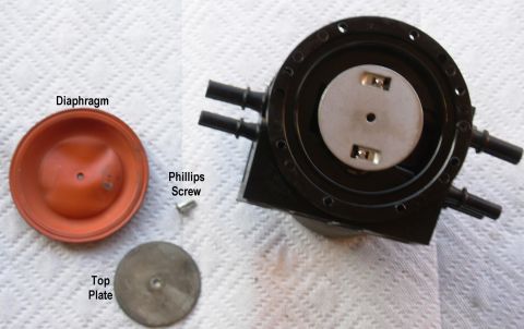
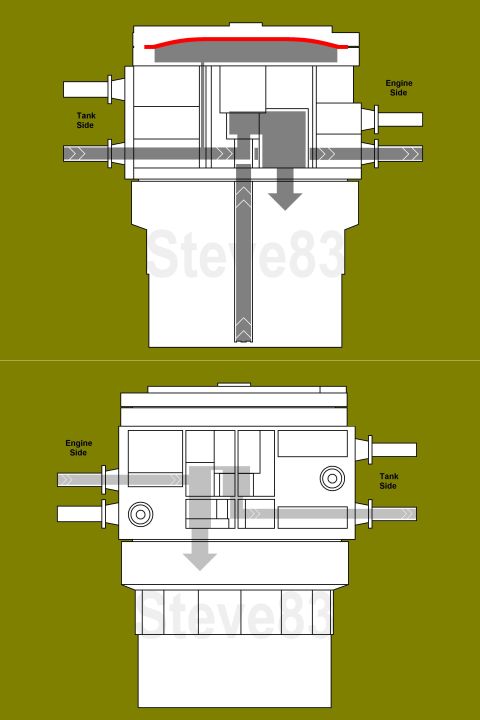
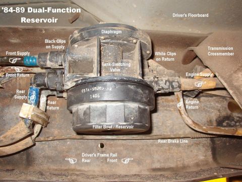
'84-89 Fuel Reservoirs
From 1983 Ford Bronco “That dirty old truck” — documented by Steve83.
37 photos
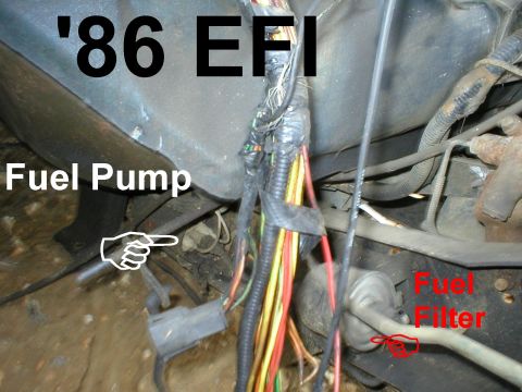
![1983 Ford Bronco - Early High-Pressure Fuel Pump & Filter IF THE IMAGE IS TOO SMALL, click it. [url=https://www.supermotors.net/registry/media/1169342] https:…](https://www.supermotors.net/thumb/894691-480.jpg)
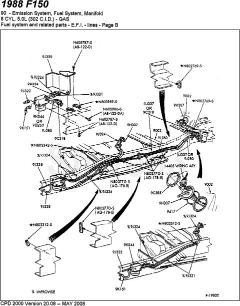
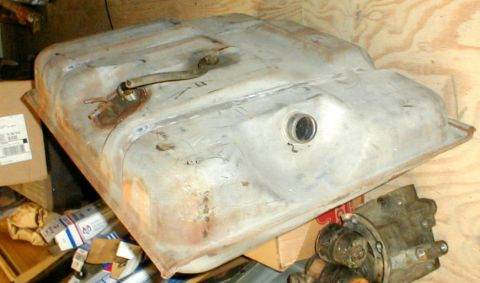
![1983 Ford Bronco - '86 F-series Fuel Tanks IF THE IMAGE IS TOO SMALL, click it. For wheelbase, see this: [url=http://www.supermotors.net/registry/media/72354]…](https://www.supermotors.net/thumb/754907-480.jpg)