Home/
Registry/
Ford/
Bronco/
1987-1991/
“Eddie Bauer”/
Photo
supermotors.net/registry/media/1007048
1990 Ford Bronco Fuse Panel Diagram: Fuse Positions, Amps & Circuits (11-2)

Reference · 1987-1991 BroncoAll 10 fuse & relay charts

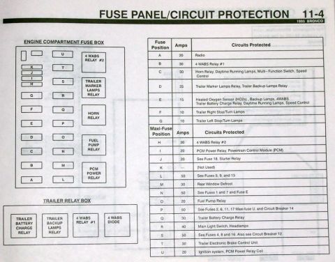
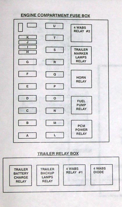
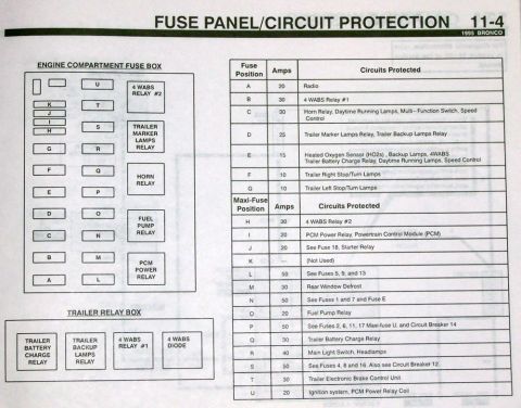
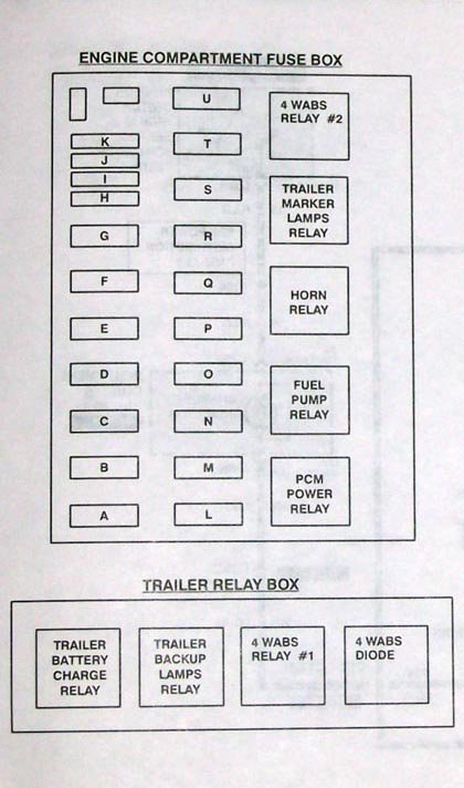

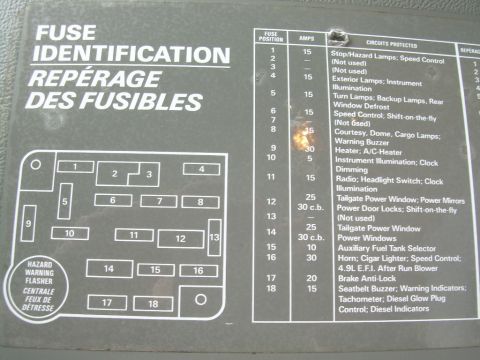












Fuse panel layout and circuit-protection chart for a Ford truck/Bronco listing each fuse position, amp rating, color code and circuits protected (stop/hazard, A/C blower, power windows, radio, ABS).
Part of 1987-1991 Ford Bronco Fuse & Relay Charts
This document is page 11-2, "Fuse Panel/Circuit Protection," from a Ford service/wiring manual, uploaded as applying to a 1990 Ford Bronco. It shows a diagram of the interior fuse panel layout with fuse positions 1-18 and the location of the round turn signal flasher at the panel's upper right corner. An accompanying table lists each fuse position, its amperage, and the circuits it protects, for example, fuse 1 (15A) covers stop/hazard lamps, anti-lock brakes, and speed control; fuse 9 (30A) covers the A/C-heater blower motor relay coil and A/C clutch; fuses 12 and 14 are 30-amp circuit breakers for power door locks/tailgate window and power windows respectively. Positions 2, 3, 7, and 13 are not used. Several entries are noted as "Bronco Only" or "Diesel Only." A legend correlates fuse amp values to blade fuse colors (4=Pink, 5=Tan, 10=Red, 15=Light Blue, 20=Yellow, 25=Natural, 30=Light Green). A "Power Distribution" text section explains that the alternator and battery connect at the starter relay hot terminal, that fuse links protect main circuits, and that fuses 1, 4, 8, 12, and 16 are hot at all times while others are powered through the ignition or main light switch.
Is this accurate? Sign in to help verify it.
Frequently asked questions
- Which fuse controls the stop and hazard lamps on a 1990 Bronco?
- Fuse position 1, a 15-amp fuse, protects the Stop and Hazard Lamps, Anti-lock Brakes, and Speed Control.
- What fuse is for the power windows?
- Fuse position 14, a 30-amp circuit breaker (30 c.b.), protects the Power Windows.
- Which fuses are hot (powered) at all times?
- Fuses 1, 4, 8, 12 and 16, along with the Ignition Switch and Main Light Switch, are powered at all times. The other fuses are powered through the Ignition Switch or the Main Light Switch.
- What do the fuse colors mean on this fuse panel?
- The color code is: 4A Pink, 5A Tan, 10A Red, 15A Light Blue, 20A Yellow, 25A Natural, 30A Light Green.
- Which fuse positions are not used?
- Fuse positions 2, 3, 7, and 13 are listed as (Not Used).
- What fuse protects the A/C and heater blower?
- Fuse position 9, a 30-amp fuse, protects the A/C-Heater Blower Motor Relay Coil and A/C Clutch.






No comments yet.