Home/
Registry/
Ford/
Bronco/
1987-1991/
“Eddie Bauer”/
Photo
supermotors.net/registry/media/1068915
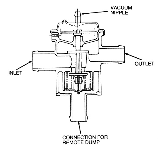
Ford Thermactor Air Bypass Valve Cutaway Diagram - Port Identification
Reference · 1987-1991 BroncoAll 110 schematics


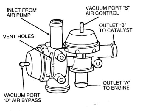


Cross-section of a secondary air bypass/diverter valve identifying the vacuum nipple, air inlet, air outlet and the remote dump connection port.
Part of 1987-1991 Ford Bronco Schematics
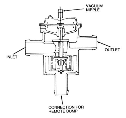
This document is a labeled cross-section (cutaway) line drawing of an air bypass valve, part of the Thermactor secondary air injection (emissions) system. The illustration shows the internal construction of the valve, including its diaphragm assembly at the top and the internal valve/seat mechanism in the body. Four external connections are called out with arrows: a VACUUM NIPPLE at the top (the vacuum signal port that actuates the diaphragm), an INLET on the left side (air supply from the air pump), an OUTLET on the right side (air passed downstream to the exhaust/thermactor plumbing), and a CONNECTION FOR REMOTE DUMP at the bottom (the port through which bypassed air is vented/dumped). The drawing contains no text beyond these four callout labels, no part numbers, torque specs, year/model applicability, or test procedures are shown. A reader can learn the physical port identification and orientation of the air bypass valve, which is useful when connecting hoses correctly or diagnosing the secondary air system. The scan was uploaded as part of an album of 1990 Ford Bronco emissions diagrams, though the drawing itself does not state a vehicle application.
Is this accurate? Sign in to help verify it.
Frequently asked questions
- What ports are shown on the air bypass valve in this diagram?
- Four connections are labeled: a vacuum nipple on top, an inlet on the left, an outlet on the right, and a connection for remote dump on the bottom.
- Where is the vacuum nipple located on the air bypass valve?
- The vacuum nipple is at the top of the valve, above the diaphragm assembly.
- Where does the remote dump connection attach?
- The connection for remote dump is at the bottom of the valve body, per the diagram callout.
- Does this diagram show the internal construction of the valve?
- Yes, it is a cutaway/cross-section drawing showing the diaphragm assembly and internal valve mechanism, though only the four external ports are labeled.






No comments yet.