Home/
Registry/
Ford/
Bronco/
1987-1991/
“Eddie Bauer”/
Photo
supermotors.net/registry/media/1068900
Ford Thermactor Combination Valve Diagram - Air Bypass/Control Ports Labeled

Reference · 1987-1991 BroncoAll 11 vacuum routing diagrams


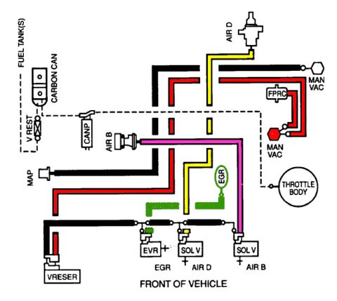
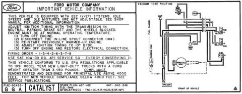
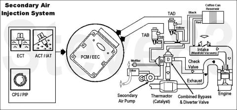



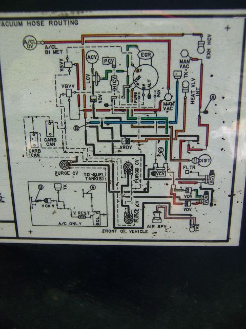












Secondary air injection combination/bypass valve showing inlet from air pump, vacuum port S (air control), port D (air bypass), outlet B to catalyst and outlet A to engine.
Part of 1987-1991 Ford Bronco Vacuum Routing Diagrams
This document is a labeled line drawing of a Thermactor secondary air system combination (bypass/diverter) valve, as used in Ford emissions systems. The illustration identifies six key features of the valve with callout arrows: the inlet from the air pump (the large upper tube), vacuum port "S" for air control (a small nipple on top of the diaphragm housing), outlet "B" to catalyst (side tube), outlet "A" to engine (bottom tube), vent holes in the valve body, and vacuum port "D" for air bypass (small nipple on the bypass diaphragm at left). The diagram lets a reader identify which hose or tube connects where when servicing or diagnosing the secondary air injection (Thermactor) system: pressurized air enters from the air pump and is routed either to the exhaust manifold/engine (outlet A), to the catalytic converter (outlet B), or vented/bypassed, depending on the vacuum signals applied to ports S and D. It contains no part numbers, torque specs, year/model statements, or test procedures, it is purely a component identification drawing useful for correctly connecting vacuum lines and air tubes on the combination valve.
Is this accurate? Sign in to help verify it.
Frequently asked questions
- What are the two vacuum ports on the Thermactor combination valve?
- Vacuum port "S" (air control), located on top of the valve, and vacuum port "D" (air bypass), located on the side diaphragm.
- Where do outlets "A" and "B" on the combination valve go?
- Outlet "A" routes air to the engine, and outlet "B" routes air to the catalyst (catalytic converter).
- Where does air enter the combination valve?
- Through the large inlet tube at the top, which comes from the air pump.
- Does the combination valve have vents?
- Yes, the drawing shows vent holes in the valve body between the bypass diaphragm and the main housing.






No comments yet.