Home/
Registry/
Ford/
Bronco/
1987-1991/
“Eddie Bauer”/
Photo
supermotors.net/registry/media/1077980
Ford Canister Purge Regulator Valve (CANP 9C915) Test Procedure - Figure 11

Reference · 1987-1991 BroncoAll 95 service procedures


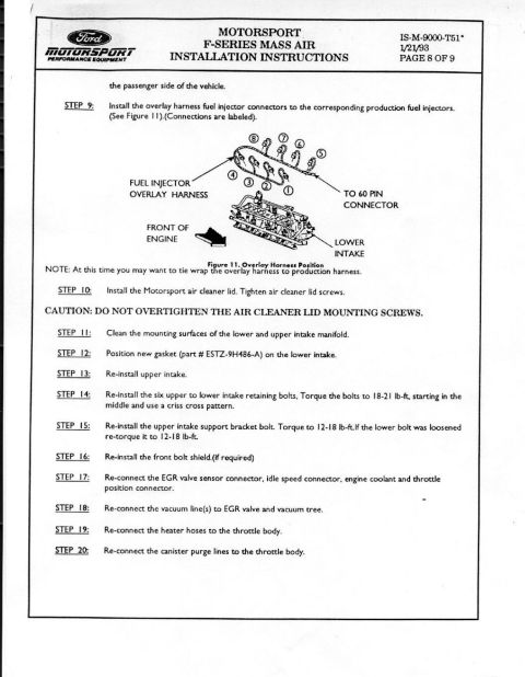










Service procedure for testing the canister purge regulator valve, with voltage/vacuum test steps and a labeled drawing of the valve (Figure 11).
Part of 1987-1991 Ford Bronco Service Procedures
This document is a one-page service procedure describing how to test the Canister Purge Regulator Valve (part reference 9C915), a component of the evaporative emissions control system. Two test steps are given. First, with the valve de-energized, the technician applies 5 in-Hg of vacuum to the "vacuum source" port; a good valve should not pass air, and if it does, the valve must be replaced. Second, while applying 9 to 14 volts DC to the valve, the valve should open and pass air; if it does not, the valve should be replaced. The page includes Figure 11, a line drawing of the Canister Purge Regulator Valve showing three ports labeled CANISTER, CARB, and VACUUM SOURCE, with drawing reference number A9386-A. The document gives a reader the pass/fail criteria for bench-testing this solenoid-operated purge valve using only a hand vacuum pump and a DC voltage source. It was uploaded as part of an album of 1990 Ford Bronco emissions system documents, though the page itself does not state a specific vehicle year, model, or engine.
Is this accurate? Sign in to help verify it.
Frequently asked questions
- How do I test the Canister Purge Regulator Valve (9C915)?
- With the valve de-energized, apply 5 in-Hg of vacuum to the "vacuum source" port, the valve should not pass air. Then apply 9 to 14 volts DC to the valve, it should open and pass air. If it fails either test, replace the valve.
- What voltage is used to energize the canister purge valve during testing?
- 9 to 14 volts DC. While energized, the valve should open and pass air.
- How much vacuum is applied when testing the purge valve de-energized?
- 5 in-Hg applied to the "vacuum source" port; the valve should not pass air when de-energized.
- What ports are shown on the Canister Purge Regulator Valve in Figure 11?
- Three connections are labeled: CANISTER, CARB, and VACUUM SOURCE.
- What should I do if the valve passes air while de-energized?
- Replace the valve, a de-energized valve that passes air has failed the test.






No comments yet.