Ford Taurus Turn Signal Switch & Flasher Wiring Diagram - Circuit 15A702
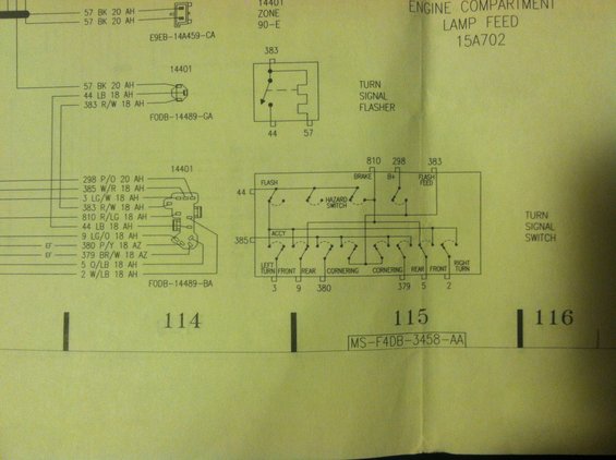
Wiring diagram of the turn signal flasher and turn signal switch circuits with color-coded wire designations.
This is a page from a Ford factory wiring diagram (sheet columns 114-116, drawing reference MS-F4DB-3458-AA) covering the turn signal circuit and the engine compartment lamp feed (circuit 15A702). It shows connector pinouts for the ignition switch/steering column area (component 14401): connector E9EB-14A459-CA with two 57 BK 20-gauge wires; connector F0DB-14489-GA with circuits 57 BK, 44 LB, and 383 R/W; and connector F0DB-14489-BA with circuits 298 P/O, 385 W/R, 3 LG/W, 383 R/W, 810 R/LG, 44 LB, 9 LG/O, 380 P/Y, 379 BR/W, 5 O/LB, and 2 W/LB, each with wire gauge and insulation codes. A schematic of the turn signal flasher shows its three terminals (383 feed, 44 and 57 outputs). The largest schematic details the turn signal switch internals, including the integrated hazard switch, with terminal assignments: 810 (brake), 298 (B+), 383 (flash feed), 44 (flash), 385 (accessory), and outputs 3 (left turn), 9 (front), 380 (rear/cornering), 379 (cornering), 5 (rear), and 2 (front/right turn). This allows tracing wire colors and pin functions for diagnosing turn signal, hazard, and brake light wiring.
Is this accurate? Sign in to help verify it.
Frequently asked questions
- What circuits connect to the turn signal flasher?
- The turn signal flasher has three terminals: circuit 383 (feed, wired as 383 R/W 18 AH), circuit 44, and circuit 57.
- What are the wire colors on the turn signal switch connector F0DB-14489-BA?
- 298 P/O 20, 385 W/R 18, 3 LG/W 18, 383 R/W 18, 810 R/LG 18, 44 LB 18, 9 LG/O 18, 380 P/Y 18, 379 BR/W 18, 5 O/LB 18, and 2 W/LB 18.
- Which terminal on the turn signal switch is the brake input?
- Circuit 810 (R/LG 18 AH) is labeled BRAKE on the turn signal switch; 298 is B+ and 383 is FLASH FEED.
- What circuit numbers feed the left and right turn outputs?
- Circuit 3 (LG/W) is LEFT TURN, circuit 9 (LG/O) is FRONT, circuit 380 (P/Y) is REAR/CORNERING, circuit 379 (BR/W) is CORNERING, circuit 5 (O/LB) is REAR, and circuit 2 (W/LB) is FRONT/RIGHT TURN.
- Is the hazard switch shown separately from the turn signal switch?
- No, the hazard switch is shown integrated within the turn signal switch schematic on this diagram.
Comments
More from this build







No comments yet.