Home/
Registry/
Ford/
Taurus/
1992-1995/
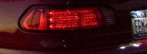
“1992 Taurus SHO - Isabel”/
Photo
supermotors.net/registry/media/786792
Ford Taurus ABS Data Link Connector C170 Pinout - Wire Colors & Circuits

Connector pinout diagram for the C170 ABS data link connector showing terminal positions and color-coded wire circuits.
This document is a simple pinout/wiring diagram for connector C170, identified as the ABS Data Link Connector. The drawing shows the connector face (an irregular, roughly diamond/hexagonal shaped connector with multiple rectangular terminal cavities) with three callouts identifying the circuits and wire colors at specific pins. Circuit 530 uses a Light Green with Yellow stripe wire (LG/Y) at the upper-right terminal. Two pins on the lower-left are labeled circuit 606 with White/Light Blue (W/LB) wires, noted as "606 (W/LB), 606 (W/LB)". Circuit 201 uses a Tan with Red stripe wire (T/R) at a lower terminal. A reader can use this diagram to locate and identify the correct wires when diagnosing the anti-lock brake system's diagnostic data link connector, for example, when connecting a scan tool or performing pin-out continuity checks on the ABS diagnostic circuit. The document contains no year, model, or part number information itself; it was uploaded to a 1992 Ford Taurus gallery alongside an EEC connector diagram, suggesting it is part of a factory wiring diagram set.
Is this accurate? Sign in to help verify it.
Frequently asked questions
- What connector is shown in this diagram?
- Connector C170, the ABS Data Link Connector.
- What wire color is circuit 530 at the ABS data link connector?
- Circuit 530 is Light Green with Yellow stripe (LG/Y).
- Which circuits use White/Light Blue wires on connector C170?
- Two pins carry circuit 606, both with White/Light Blue (W/LB) wires.
- What is the wire color for circuit 201 on the ABS data link connector?
- Circuit 201 is Tan with Red stripe (T/R).
Comments
More from this build













No comments yet.