Home/
Registry/
Ford/
Taurus/
1992-1995/
1993 Ford Taurus/
Photo
supermotors.net/registry/media/604754
Ford Taurus SHO 3.0L PCM Connector C191 60-Pin Pinout Diagram - Wire Colors

Reference · 1992-1995 TaurusAll 37 wiring diagrams
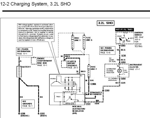
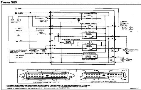
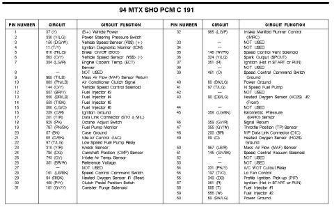
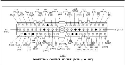

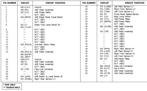

Connector pinout diagram for the 3.0L SHO powertrain control module C191 with numbered pins and color-coded circuits.
Part of 1992-1995 Ford Taurus Wiring Diagrams
This document is a pinout diagram for connector C191, the 60-pin Powertrain Control Module (PCM) connector on a Ford 3.0L SHO engine. The drawing shows the physical face of the connector with three rows of numbered cavities (pins 1-20 across the top, 21-40 in the middle, and 41-60 along the bottom). Callout lines identify the circuit number and wire color code for each populated pin, for example, pin 1 is circuit 37 (Yellow), pin 3 is circuit 150 (Dark Green/White), pin 21 is circuit 68 (Orange/Black), pin 40 carries circuit 60 (Black/Light Green), and pin 60 is also circuit 60 (Black/Light Green). Several cavities are drawn filled/blackened, indicating unused positions with no circuit. Wire colors are given in standard Ford abbreviations (Y = yellow, LG = light green, DG = dark green, T = tan, PK = pink, BR = brown, O = orange, BK = black, DB = dark blue, GY = gray, R = red, W = white, LB = light blue, P = purple). A reader can use this diagram to locate any specific PCM pin, verify wiring by circuit number and color, and perform back-probing or continuity tests on the 3.0L SHO engine management harness.
Is this accurate? Sign in to help verify it.
Frequently asked questions
- What connector does this diagram show?
- It shows connector C191, the 60-pin Powertrain Control Module (PCM) connector for the 3.0L SHO engine.
- What circuit and wire color is on PCM pin 1?
- Pin 1 is circuit 37 with a Yellow (Y) wire.
- Which circuit is on pin 40 of the C191 PCM connector?
- Pin 40 carries circuit 60 with a Black/Light Green (BK/LG) wire; pin 60 also shows circuit 60 (BK/LG).
- What wire color is circuit 883 at the PCM?
- Circuit 883 is Pink/Light Blue (PK/LB), located at pin 10 on the top row.
- Are all 60 pins of connector C191 used?
- No: several cavities are drawn as filled/blackened dots (e.g., in the middle and bottom rows), indicating unused positions with no circuit assigned.






No comments yet.