Ford Taurus Turn Signal Switch & Flasher Wiring Diagram - Circuits 15A702
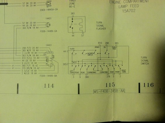
Wiring diagram of the turn signal flasher and turn signal switch circuits with color-coded wire designations.
This document is a section of a Ford electrical wiring diagram (EVTM-style schematic) covering the turn signal flasher and turn signal switch circuits, headed "Engine Compartment Lamp Feed 15A702." It shows connector pinouts for three connectors in the 14401 wiring harness: connector E9EB-14A459-CA (two circuit 57 BK 20 AH wires), connector FODB-14489-GA (circuits 57 BK 20 AH, 44 LB 18 AH, 383 R/W 18 AH), and connector FODB-14489-BA (circuits 298 P/O, 385 W/R, 3 LG/W, 383 R/W, 810 R/LG, 44 LB, 9 LG/O, 380 P/Y, 379 BR/W, 5 O/LB, 2 W/LB). The turn signal flasher is drawn with terminal 383 in and terminals 44 and 57 out. The turn signal switch internal schematic identifies inputs 810 (brake), 298 (B+), 383 (flash feed), 44 (flash) and 385 (accessory), the integrated hazard switch, and outputs to circuits 3, 9, 380 (left turn front/rear/cornering) and 379, 5, 2 (right cornering/rear/front turn). Page/grid columns 114-116 are marked, with reference MS-F4DB-3458-AA. A reader can trace wire colors, gauges and circuit numbers for turn signal and hazard lamp diagnosis.
Is this accurate? Sign in to help verify it.
Frequently asked questions
- What circuit connects the turn signal flasher to the turn signal switch?
- Circuit 383 R/W 18 (Red/White, 18 gauge) is the flash feed from the flasher to the turn signal switch; circuit 44 LB 18 (Light Blue) carries the flash output, and circuit 57 BK 20 (Black) is shown on the other flasher terminal.
- Which circuits feed the turn signal switch?
- Terminal 810 is the BRAKE input, 298 is B+, 383 is FLASH FEED, 44 is FLASH, and 385 is the ACCY (accessory) input.
- What are the output circuits from the turn signal switch to the lamps?
- Left side: circuit 3 (left turn front), 9 (rear), 380 (cornering). Right side: 379 (cornering), 5 (rear), 2 (right turn front).
- What wire colors are used at connector FODB-14489-BA?
- 298 P/O 20, 385 W/R 18, 3 LG/W 18, 383 R/W 18, 810 R/LG 18, 44 LB 18, 9 LG/O 18, 380 P/Y 18, 379 BR/W 18, 5 O/LB 18, and 2 W/LB 18.
- Is the hazard switch part of the turn signal switch?
- Yes: the schematic shows the hazard switch drawn inside the turn signal switch assembly, tying the flash feed (383) to the turn lamp circuits when activated.
Comments
More from this build







No comments yet.