Home/
Registry/
Ford/
Taurus/
1992-1995/
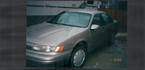
1993 Ford Taurus/
Photo
supermotors.net/registry/media/602188
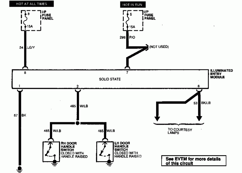
1993 Ford Taurus Illuminated Entry Module Wiring Diagram - Fuses & Wire Colors
Reference · 1992-1995 TaurusAll 37 wiring diagrams
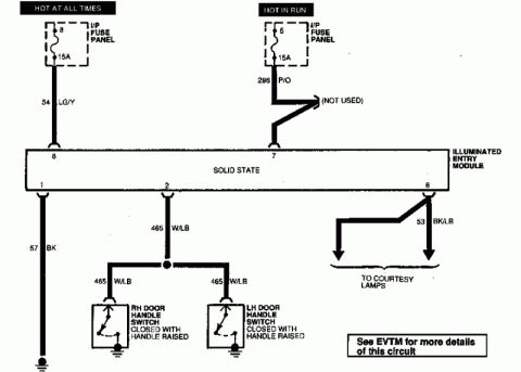
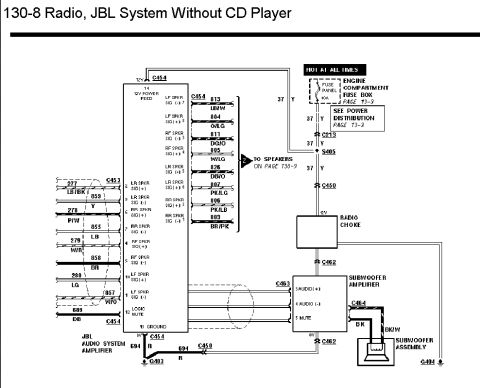
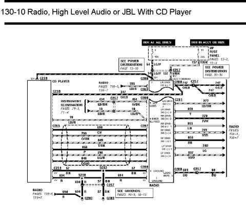
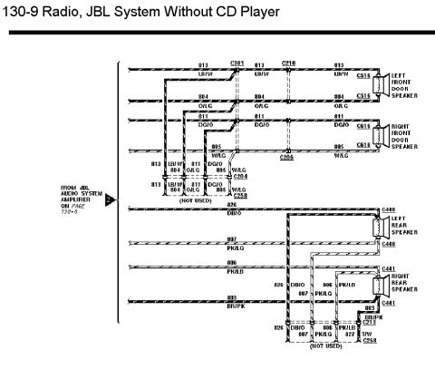


Wiring diagram of the illuminated entry module showing door handle switches and courtesy lamp circuits.
Part of 1992-1995 Ford Taurus Wiring Diagrams
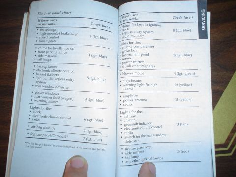
This wiring diagram shows the illuminated entry system circuit, filed by the uploader for a 1993 Ford Taurus. Power comes from two sources on the instrument panel (I/P) fuse panel: Fuse 8 (15A, hot at all times) feeding pin 8 of the solid-state Illuminated Entry Module via circuit 54 LG/Y (light green/yellow), and Fuse 5 (15A, hot in run) feeding pin 7 via circuit 298 P/O (purple/orange), with one branch of that circuit marked as not used. Pin 1 of the module grounds through circuit 57 BK (black). Pin 2 connects via circuit 465 W/LB (white/light blue) to both the right-hand and left-hand door handle switches, each of which closes to ground when the door handle is raised, triggering the module. Pin 6 outputs on circuit 53 BK/LB (black/light blue) to the courtesy lamps. A note directs the reader to the EVTM (Electrical and Vacuum Troubleshooting Manual) for more details. The diagram allows a technician to identify fuse locations and ratings, wire circuit numbers and colors, module pinout, switch operation, and ground points for diagnosing illuminated entry or courtesy lamp problems.
Is this accurate? Sign in to help verify it.
Frequently asked questions
- Which fuses power the illuminated entry module on a 1993 Ford Taurus?
- Fuse 8 (15A, hot at all times) feeds module pin 8 via circuit 54 LG/Y, and Fuse 5 (15A, hot in run) feeds module pin 7 via circuit 298 P/O, both in the I/P fuse panel.
- What wire connects the door handle switches to the illuminated entry module?
- Circuit 465 W/LB (white/light blue) runs from module pin 2 to both the RH and LH door handle switches, which close to ground when the handle is raised.
- Which wire feeds the courtesy lamps from the illuminated entry module?
- Pin 6 of the module outputs on circuit 53 BK/LB (black/light blue) to the courtesy lamps.
- How is the illuminated entry module grounded?
- Module pin 1 is grounded through circuit 57 BK (black).
- When do the door handle switches close in this circuit?
- Both the RH and LH door handle switches are closed with the handle raised, grounding circuit 465 W/LB to trigger the module.

No comments yet.