Home/
Registry/
Hyundai/
Genesis Coupe/
2010-2016/
“Coupe”/
Photo
supermotors.net/registry/media/1025649
2010 Hyundai Genesis V6 MAF Sensor Location & 5-Pin Connector Pinout Diagram
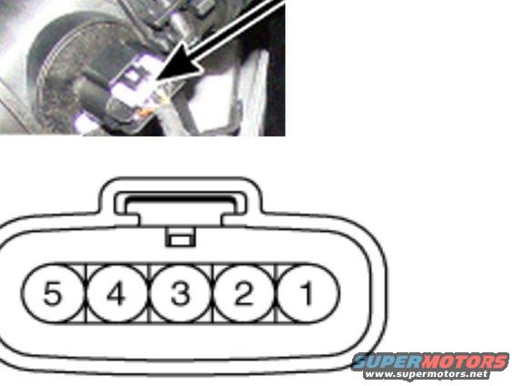
Service figure showing a numbered 5-terminal electrical connector with an inset photo of the connector on the vehicle.
Part of 2010-2016 Hyundai Genesis Coupe Manual Pages
This document consists of two images related to a mass air flow (MAF) sensor on a Hyundai Genesis (uploader identifies it as the V6 MAF combination sensor). The top image is a photograph of the engine bay showing the sensor mounted in the air intake tract, with a large arrow indicating its exact location for identification during diagnosis or removal. The bottom image is a connector pinout diagram showing the face view of the sensor's 5-pin electrical connector, with terminal cavities numbered 5, 4, 3, 2, 1 from left to right and a locking tab at the top center of the housing. The document contains no wire colors, pin function descriptions, part numbers, torque specifications, or year/model text, it serves purely as a visual locator and terminal numbering reference. A technician can use this page to confirm which terminal is which when back-probing or testing the MAF sensor connector, since terminal orientation is often ambiguous without a face-view diagram. Any specific pin functions (power, ground, signal, intake air temperature) would need to come from an accompanying wiring diagram page in the same service manual set.
Is this accurate? Sign in to help verify it.
Frequently asked questions
- How many pins does the Hyundai Genesis V6 MAF sensor connector have?
- The connector diagram shows a 5-pin connector, with cavities numbered 5, 4, 3, 2, 1 from left to right when viewed face-on.
- How are the terminals numbered on the MAF connector?
- Viewing the connector face with the locking tab at the top, the terminals are numbered 5, 4, 3, 2, 1 from left to right (pin 1 on the right).
- Does this document show where the MAF sensor is located?
- Yes, the photograph at the top uses a large arrow to point out the sensor's mounting location in the air intake area of the engine bay.
- Does this page list wire colors or pin functions for the MAF sensor?
- No. Only the terminal numbering (1 through 5) is shown; no wire colors, pin functions, or part numbers appear in the document.
Comments
More from this build









No comments yet.