Home/
Registry/
Hyundai/
Genesis Coupe/
2010-2016/
“Coupe”/
Photo
supermotors.net/registry/media/887468
2010 Hyundai Genesis Coupe Headlamp Leveling Unit & Actuator Locations

Reference · 2010-2016 Genesis CoupeAll 24 manual pages
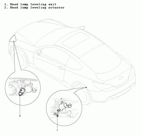








Manual component-location figure showing the headlamp leveling unit and leveling actuator positions on a coupe.
Part of 2010-2016 Hyundai Genesis Coupe Manual Pages
This document is a component location diagram for the headlamp leveling system of a two-door coupe (uploaded as applying to a 2010 Hyundai Genesis Coupe). The page shows a line illustration of the vehicle from the rear three-quarter view with two magnified callout circles identifying the locations of the system's components. Item 1, the head lamp leveling unit, is shown mounted on a bracket with a linkage at the rear suspension near the rear wheel arch; this is the sensor that detects vehicle ride height/pitch. Item 2, the head lamp leveling actuator, is shown installed on the back of the headlamp assembly at the front of the vehicle; this actuator adjusts the headlamp beam aim. A reader can learn where both headlamp leveling components are physically located on the vehicle for inspection, diagnosis, or replacement. The document contains no part numbers, torque specifications, wiring information, or explicit year/model text, it consists solely of the two-item legend and the annotated illustration.
Is this accurate? Sign in to help verify it.
Frequently asked questions
- Where is the head lamp leveling unit located?
- The diagram shows the head lamp leveling unit (item 1) mounted on a bracket with a linkage at the rear suspension area, near the rear wheel arch.
- Where is the head lamp leveling actuator located?
- The head lamp leveling actuator (item 2) is shown mounted on the back of the headlamp assembly at the front of the vehicle.
- What components make up the headlamp leveling system in this diagram?
- Two components are identified: 1. Head lamp leveling unit and 2. Head lamp leveling actuator.

No comments yet.