Home/
Registry/
Hyundai/
Genesis Coupe/
2010-2016/
“Coupe”/
Photo
supermotors.net/registry/media/1035119
2010 Hyundai Genesis Coupe Infinity Amplifier Pinout - 26 & 16 Pin Connectors

Reference · 2010-2016 Genesis CoupeAll 24 manual pages
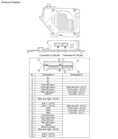








Service-manual page showing an external audio amplifier with a pin-assignment table for its 26-pin and 16-pin connectors.
Part of 2010-2016 Hyundai Genesis Coupe Manual Pages
This document is a service-manual page showing the external audio amplifier for a Hyundai Genesis, including an illustration of the amplifier housing and its two connectors: Connector A (26-pin) and Connector B (16-pin). A pin diagram shows the numbering orientation of both connectors (pins 1-13 top and 14-26 bottom for Connector A; pins 1-8 top and 9-16 bottom for Connector B). The accompanying table lists every pin assignment. Connector A carries three B+ power pins (1-3), low-level audio inputs (front left/right and rear left/right, + and -), the amplifier ON/OFF signal, Speed input, Mode EQ select, three grounds (14-16), and speaker-level outputs for rear door right (CH 8), Sub 1 (CH 5), and Sub 2 (CH 6). Connector B carries speaker outputs (+ and -) for front left (CH 1), front right (CH 2), front center (CH 3), and rear door left (CH 4). A reader can use this page to identify amplifier wiring for troubleshooting, bypassing, or integrating aftermarket audio equipment with the factory external (Infinity-type) amplifier in an 8-speaker system.
Is this accurate? Sign in to help verify it.
Frequently asked questions
- How many pins do the external amplifier connectors have?
- Connector A has 26 pins and Connector B has 16 pins.
- Which pins provide power and ground to the amplifier?
- Connector A pins 1, 2 and 3 are B+ power, and pins 14, 15 and 16 are GND.
- Where are the front speaker outputs on the amplifier?
- On Connector B: Front left + (CH 1) is pin 8 and Front left - is pin 16; Front right + (CH 2) is pin 7 and Front right - is pin 15.
- Which pins are the subwoofer outputs?
- On Connector A: Sub 1 + (CH 5) is pin 13 and Sub 1 - is pin 26; Sub 2 + (CH 6) is pin 12 and Sub 2 - is pin 25.
- What pin turns the amplifier on?
- The ON/OFF signal is on Connector A, pin 8.

No comments yet.