Home/
Registry/
Ford/
Bronco/
1978-1979/
1979 Ford Bronco/
Photo
supermotors.net/registry/media/1032625
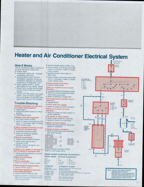
1979 Ford Bronco F100-F350 Charging System Troubleshooting & Alternator Tests
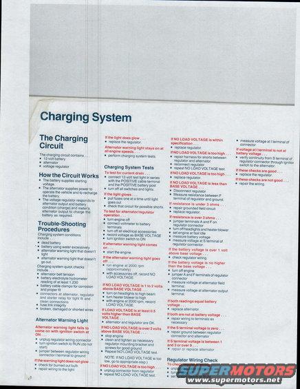
Ford manual Charging System page: how the alternator/voltage regulator/battery circuit works plus quick checks (belt tension, hydrometer >=1.230) and no-load voltage troubleshooting steps.
This page is a service procedure document titled "Charging System," part of a multi-page Ford Bronco/F100–F350 reference set. It explains that the charging circuit contains a 12-volt battery, alternator, and voltage regulator, and describes how each component works. It lists common charging system trouble conditions (dead battery, battery using water excessively, alternator warning light problems) and quick checks such as belt tension, battery electrolyte hydrometer reading of at least 1.230, cable clamp corrosion, connector fit, fuse link integrity, and damaged wiring. Step-by-step diagnostic procedures follow: alternator warning light checks (jumpering the regulator connector I terminal to ground), a current drain test using a 12-volt test light in series with the positive battery cable, and alternator/regulator operation tests comparing BASE VOLTAGE, NO LOAD VOLTAGE (at ~2000 rpm), and LOAD VOLTAGE (headlights on high beam, heater blower on high). Decision points guide the reader through outcomes—e.g., if LOAD VOLTAGE is at least 0.5 volts above BASE VOLTAGE the alternator and regulator are OK; resistance under 3 ohms at the F terminal indicates a grounded field circuit; equal field and output terminal readings mean replace the alternator. A final Regulator Wiring Check section covers measuring voltage at the I terminal and verifying continuity through the ignition switch.
Is this accurate? Sign in to help verify it.
Frequently asked questions
- What components make up the charging circuit?
- According to the document, the charging circuit contains a 12-volt battery, an alternator, and a voltage regulator.
- How do I test for a current drain?
- Connect a 12-volt test light in series with the POSITIVE cable terminal and the POSITIVE battery post, then turn off all switches and lights. If the light glows, pull fuses one at a time until the light goes out, then check that circuit for possible shorts.
- What indicates the alternator and regulator are OK during the load test?
- If LOAD VOLTAGE (recorded at 2000 rpm with headlights on high beam and heater blower on high) is at least 0.5 volts higher than BASE VOLTAGE, the alternator and regulator are OK.
- What should the battery electrolyte hydrometer reading be?
- The quick checks list a battery electrolyte hydrometer reading of at least 1.230.
- What if resistance between the regulator F terminal and ground is under 3 ohms?
- The document says to repair the grounded field circuit and replace the regulator.
Comments
More from this build


No comments yet.