Home/
Registry/
Ford/
F-250/
1987-1991/
1988 Ford F-250/
Photo
supermotors.net/registry/media/1036674
Ford PMGR Starter Wiring Diagram - Solenoid, Relay & Cable Instructions
Reference · 1987-1991 F-250All 32 wiring diagrams




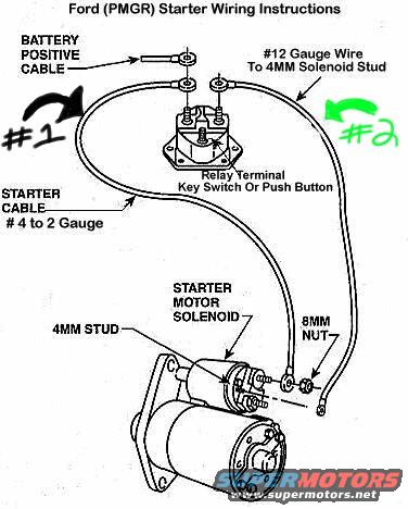
Starter wiring instructions diagram showing battery positive cable, starter cable, and solenoid stud connections.
Part of 1987-1991 Ford F-250 Wiring Diagrams
This document is a wiring instruction diagram for a Ford PMGR (Permanent Magnet Gear Reduction) starter. It illustrates how to connect a PMGR-style starter motor to the vehicle's starter relay (fender-mounted solenoid) and battery. The diagram shows the battery positive cable attaching to one large stud of the starter relay. A #12 gauge wire (marked with annotation #2) runs from the relay's output side down to the 4MM solenoid stud on the starter motor solenoid, secured with an 8MM nut. The main starter cable, specified as #4 to #2 gauge, runs from the relay (annotation #1) to the large terminal on the starter motor solenoid. The relay terminal labeled 'Relay Terminal Key Switch Or Push Button' identifies where the ignition key switch or a push button trigger wire connects. Callouts identify the 4MM stud and 8MM nut on the starter solenoid. A reader can learn the proper wire gauges (#12 gauge trigger wire, #4-#2 gauge main cable), the connection points on both the fender relay and the starter-mounted solenoid, and the hardware sizes involved when retrofitting or wiring a Ford PMGR starter. No specific model years, engines, or part numbers are stated on the document.
Is this accurate? Sign in to help verify it.
Frequently asked questions
- What gauge wire goes to the 4MM solenoid stud on a Ford PMGR starter?
- The diagram specifies #12 gauge wire from the relay to the 4MM solenoid stud on the starter motor solenoid.
- What size should the main starter cable be for a Ford PMGR starter?
- The diagram calls for a starter cable of #4 to #2 gauge.
- What size nut secures the wire to the starter solenoid stud?
- An 8MM nut secures the #12 gauge wire to the 4MM stud on the starter motor solenoid.
- Where does the key switch or push button connect on the starter relay?
- It connects to the small relay terminal labeled 'Relay Terminal Key Switch Or Push Button' on the fender-mounted relay.
- Where does the battery positive cable attach in this PMGR starter wiring?
- The battery positive cable attaches to one of the large studs on the starter relay, shown at the top of the diagram.






No comments yet.