Home/
Registry/
Ford/
Taurus/
1996-1999/
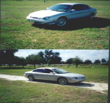
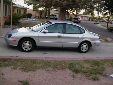
1997 Ford Taurus/
Photo
supermotors.net/registry/media/1043289
2002 Ford Taurus/Sable PCM Connector C175 Pinout (Pins 1-40) - Duratec Wiring

Service manual connector view of PCM connector C175 with a pin-by-pin circuit and function table.
This is a page (150-10, "Connector Views") from a 2002 Ford Taurus/Mercury Sable wiring reference showing connector C175, the 104-pin Powertrain Control Module (PCM) connector (base part 12B637; PCM component number 12A650, item A147). A drawing of the connector face indicates the pin numbering layout (pins 1-26 top, 27-53 and 79-104 rows, etc., figure F104001). Two tables list pins 1-21 and 22-40 with circuit numbers, wire colors, and circuit functions. Notable circuits include shift solenoids A and B (237 OG/YE, 315 VT/OG), the MIL control (658 PK/LG), DTR sensor TR1 (1144 YE/BK), turbine shaft speed sensor (970 DG/WH), fuel pump/fuel gauge sender (29 YE/WH), SCP Bus + and, (914 TN/OG, 915 PK/LB), crankshaft position sensor + and, (350 GY, 349 DB), grounds (570 BK/WH, 57 BK), ignition coil A cylinders 1 and 5 (850 YE/BK), knock sensor (1273 YE), HO2S #12 (94 RD/BK), MAF signal return (968 TN/LB), TFT, ECT (354 LG/RD), IAT (743 GY), and fuel pump driver module input (238 DG/YE). Many pins are marked "not used." A reader can identify wire colors and functions for PCM pins 1-40 on this connector.
This document covers 2002, which may differ from this 1997 Ford Taurus.
Is this accurate? Sign in to help verify it.
Frequently asked questions
- What connector is shown in this diagram?
- Connector C175, the Powertrain Control Module (PCM) (12A650) connector, base part number 12B637, item A147, from the Taurus/Sable '02 connector views section (page 150-10).
- Which PCM pins are the SCP Bus circuits?
- Pin 15 is SCP Bus - (circuit 915, PK/LB) and pin 16 is SCP Bus + (circuit 914, TN/OG).
- Which pins connect to the crankshaft position sensor?
- Pin 21 is crankshaft position sensor (6C315) + on circuit 350 (GY), and pin 22 is crankshaft position sensor (6C315) - on circuit 349 (DB).
- What wire color is the ECT sensor input to the PCM?
- Pin 38, circuit 354 (LG/RD), is the Engine Coolant Temperature (ECT) sensor (12A648) input.
- Which pins are grounds on this PCM connector?
- Pin 24 (circuit 570, BK/WH) and pin 25 (circuit 57, BK) are Ground.
Comments
More from this build







No comments yet.