Home/
Registry/
Ford/
Taurus/
1996-1999/
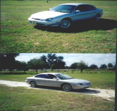
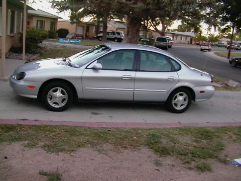
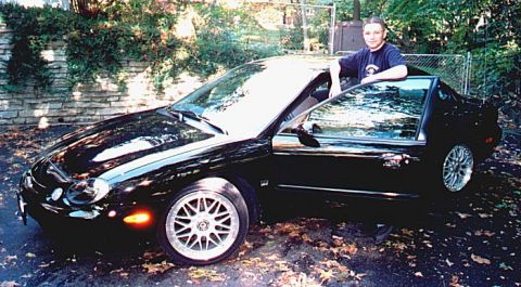
1997 Ford Taurus/
Photo
supermotors.net/registry/media/1043288
Ford Taurus 3.0L Duratec Camshaft/ECT/OSS Sensor Wiring Diagram - PCM VREF

Reference · 1996-1999 TaurusAll 33 wiring diagrams
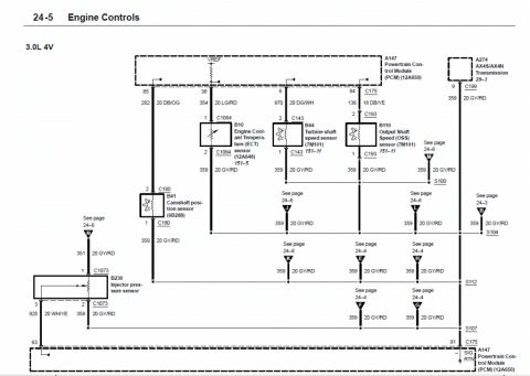
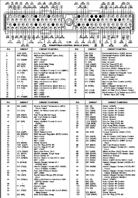
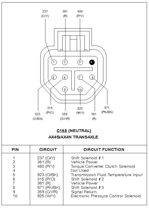
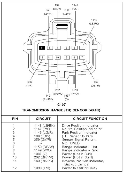
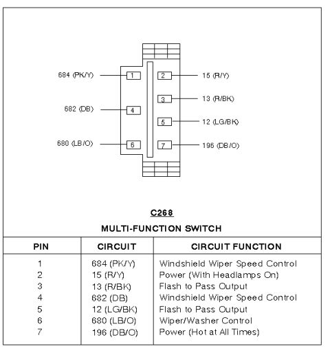
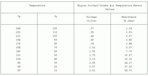
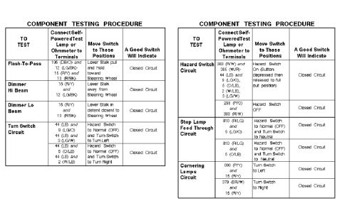
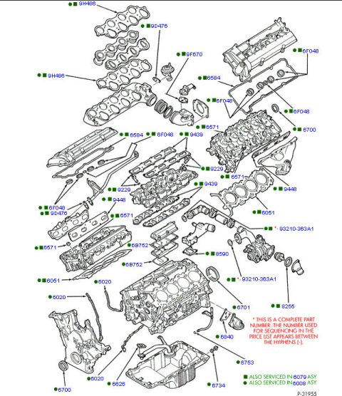
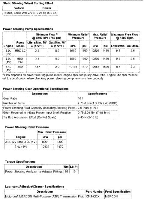

Engine controls wiring diagram for a 3.0L 4V showing PCM connections to coolant, shaft speed and injector sensors with color-coded circuits.
Part of 1996-1999 Ford Taurus Wiring Diagrams
This is page 24-5, 'Engine Controls,' of a Ford wiring diagram covering the 3.0L 4V (Duratec) engine. It shows the sensor reference voltage (VREF) and signal return (SIG RTN) wiring between the A147 Powertrain Control Module (PCM, part 12A650) and several engine/transmission sensors: the B10 Engine Coolant Temperature (ECT) sensor (12A648) via connector C1064, the B44 Turbine Shaft Speed sensor (7M101) via C143, the B110 Output Shaft Speed (OSS) sensor (7M101) via C193, the B41 Camshaft Position sensor (6B288) via C180, and the B230 Injector Pressure sensor via C1073. PCM pins shown include 85 (circuit 282, 20 DB/OG), 38 (circuit 354, 20 LG/RD), 6 (circuit 970, 20 DG/WH), 84 (circuit 136, 18 DB/YE via C175), 9 (circuit 359, 20 GY/RD to the A274 AX4S/AX4N transmission via C199), 63, and 91 (SIG RTN via C175). The shared signal return circuit 359 (20 GY/RD wire) runs through splices S100, S104, S107, and S112, with branch takeouts (letters B, E, F, G, H, J, K, L, M, N) cross-referencing pages 24-3, 24-4, and 24-6. Useful for diagnosing sensor reference and return circuits on Duratec-equipped vehicles.
Is this accurate? Sign in to help verify it.
Frequently asked questions
- What PCM pin does the camshaft position sensor return connect to on the 3.0L 4V?
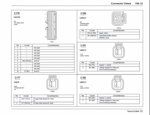
- The B41 Camshaft Position Sensor (6B288) connects through connector C180; pin 1 carries circuit 359 (20 GY/RD), the shared signal return that runs to PCM pin 91 (SIG RTN) via connector C175.
- What wire color is the signal return circuit 359?
- Circuit 359 is a 20-gauge GY/RD (gray/red) wire shared by the ECT, turbine shaft speed, output shaft speed, camshaft position, and injector pressure sensors.
- Which connector is used for the Engine Coolant Temperature (ECT) sensor?
- The B10 ECT sensor (part 12A648) uses connector C1064; pin 1 is the signal side and pin 2 is circuit 359, 20 GY/RD signal return.
- What circuit and wire feed the Output Shaft Speed (OSS) sensor signal to the PCM?
- The B110 OSS sensor (7M101) signal runs from connector C193 pin 2 through PCM pin 84 via C175 on circuit 136, an 18-gauge DB/YE wire.
- What transmission connections are shown on this diagram?
- PCM pin 9 connects via C199 on circuit 359 (20 GY/RD) to the A274 AX4S/AX4N transmission (referenced to page 29-3), and the diagram includes the turbine shaft speed (B44) and output shaft speed (B110) sensors.



No comments yet.