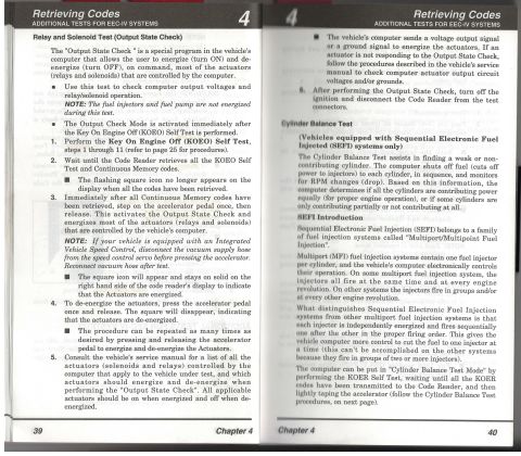
Home/
Registry/
Ford/
Bronco/
1992-1996/
1996 Ford Bronco/
Photo
supermotors.net/registry/media/1120969
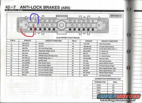
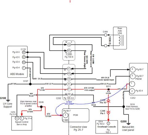
Wiring diagram for the C119 4WABS Control Module, detailing pin assignments and circuit functions for a Bronco.
C119 4WABS Control Module PIN # CIRCUIT CIRCUIT FUNCTION PIN # CIRCUIT I CIRCUIT FUNCTION 1 530 (LG/Y) Ground 27 510 (T/R) Hear Dump Valve 53 (LG/Y) Ground 23 960 (BK/LB) Chassis Rolls Databus 498 (PK) RH Front Dump Velve I 29 539 (PK/LB) Pump Motor Relay Coil () 606 (W/LB) Diagnostic Trigger Circuit 30 886 (O/BK) GSwltch #2 532 (ON) Valve Reference 31 887 (Y) GSwitch #1 603 (DC) 4WABS Failure Warning Lamp I 32 836 (GM) GSwitch Status 599 (PK/LG) 4WABS Relay Coil () 499 (GY/BK) Rear lso Valve ignition Feed 497 (W) RH Front lso Valve 601 (LB/PK) 519 (LG/BK) 523 (R/PK) 51s (Y/BK) 521 (1/0) 522 (T/eK) 496 (0) Rear Sensor (Low) Rear Sensor (High) RH Front Sensor (Low) LH Front Sensor (High) LH Front Sensor (Low) LH Front Dump Valve Brake ON/OFF Switch RH Front Sensor (High) Motor Speed Sensor High Motor Speed Sensor Low Vehicle Speed Output LH Front lso Valve 51 1 (LG) 514 MR) 604 (OIR) 491 (O/Le) 495 (T) CONNECTOR REFERENCE LIST CONNECTOR 60
Comments
More from this build


No comments yet.