Home/
Registry/
Ford/
Bronco/
1992-1996/
1996 Ford Bronco/
Photo
supermotors.net/registry/media/1120970
1994 Ford Bronco 4WABS ABS Control Module C119 Connector Pinout - EVTM 42-7

Reference · 1992-1996 BroncoAll 411 wiring diagrams
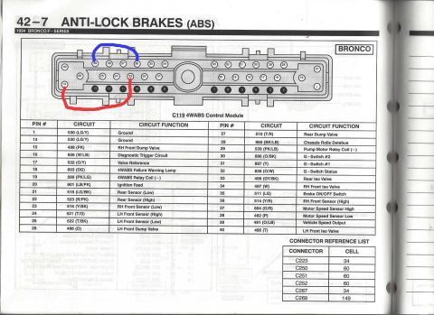
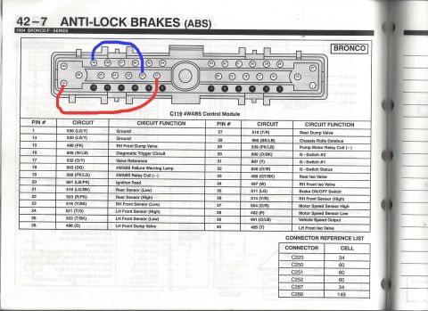
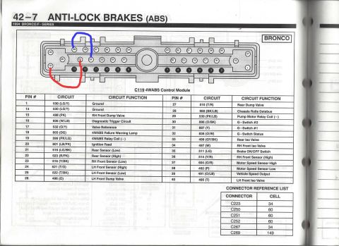
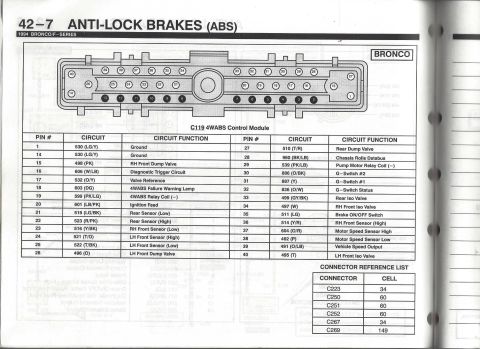
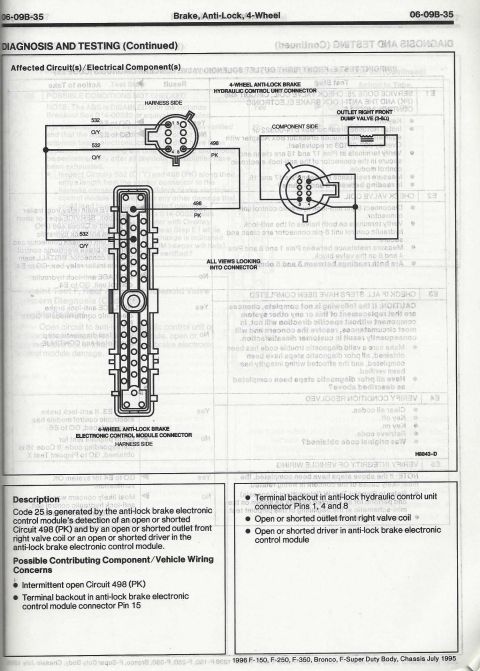
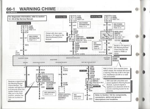

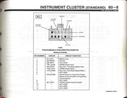
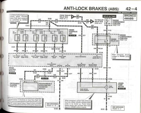
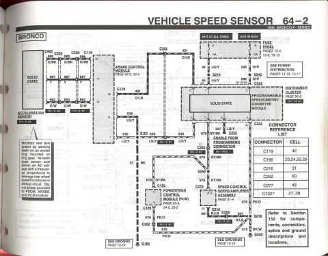






4WABS control module connector C119 pinout (1994 Bronco/F-Series) with circled upper and lower pin rows; full 40-pin circuit, wire-color and function table.
Part of 1992-1996 Ford Bronco Wiring Diagrams
This is page 42-7 of the 1994 Ford Bronco/F-Series Electrical & Vacuum Troubleshooting Manual (EVTM), covering the Anti-Lock Brakes (ABS) system. The page shows the C119 4WABS (four-wheel anti-lock brake system) Control Module connector for the Bronco: a 40-pin connector illustration with pin locations numbered 1-40 (two pin groups have been hand-highlighted in blue and red by the uploader). Below the drawing, a full pinout table lists each pin number, its circuit number and wire color code, and the circuit function, for example pin 1/14 = circuit 530 (LG/Y) Ground, pin 18 = 603 (DG) 4WABS Failure Warning Lamp, pin 20 = 601 (LB/PK) Ignition Feed, pins 21-25 = rear and front wheel speed sensor high/low circuits, and pins 15, 26, 27, 33, 34, 40 = the front/rear dump and isolation valve circuits. A Connector Reference List cross-references connectors C223, C250, C251, C252, C267 and C269 to their diagram cells (34, 60, 60, 60, 34, 149). A reader can use this page to identify wire colors and functions when diagnosing or testing the 4WABS control module harness on a 1994 Bronco.
This document covers 1994, which may differ from this 1996 Ford Bronco.
Is this accurate? Sign in to help verify it.
Frequently asked questions
- What connector does this diagram cover?
- C119, the 4WABS (4-wheel anti-lock brake system) Control Module connector on the 1994 Bronco, a 40-pin connector with a full pin-by-pin circuit table.
- Which pins are ground on the 1994 Bronco ABS module?
- Pins 1 and 14, both circuit 530 (LG/Y: light green/yellow).
- Which pin is the ignition feed to the 4WABS module?
- Pin 20, circuit 601 (LB/PK: light blue/pink), listed as Ignition Feed.
- What are the rear wheel speed sensor circuits?
- Pin 21 is circuit 519 (LG/BK) Rear Sensor (Low) and pin 22 is circuit 523 (R/PK) Rear Sensor (High).
- Which pin drives the ABS failure warning lamp?
- Pin 18, circuit 603 (DG: dark green), labeled 4WABS Failure Warning Lamp.






No comments yet.