Home/
Registry/
Ford/
Bronco/
1992-1996/
1996 Ford Bronco/
Photo
supermotors.net/registry/media/1120970

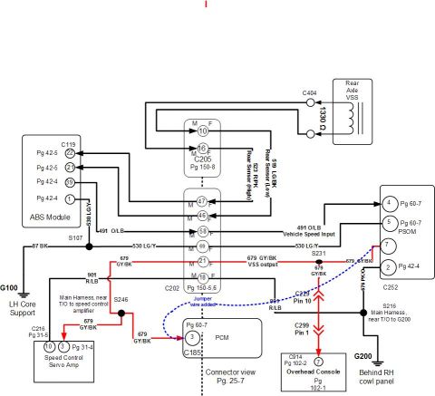
Diagram details the wiring and circuit functions for the 4WABS control module on a Bronco.
427 ANTI-LOCK BRAKES (ABS) _ C119 4WABS Control Module PIN # CIRCUIT CIRCUIT FUNCTION PIN # CIRCUIT I CIRCUIT FUNCTION 1 530 (LG/Y) Ground 27 510 (T/R) Rear Dump Valve 53 (LG/Y) Ground 23 960 (BK/LB) Chassis Rolls Databus 498 (PK) RH Front Dump Valve I 29 539 (PK/LB) Pump Motor Relay Coil () 606 (W/LB) Diagnostic Trigger Circuit 30 886 (O/BK) GSwltch #2 17 532 (ON) Valve Reference 31 887 (Y) GSwitch #1 18 603 (DC) 4WABS Failure Warning Lamp I 32 836 (GM) GSwitch Status 499 (GY/BK) Rear lso Valve 497 (W) RH Front lso Valve 51!) (LG/BK) Rear Sensor (Low) 51 1 (LG) Brake ON/OFF Switch 523 (R/PK) Rear Sensor (High) 514 (Y/R) RH Front Sensor (High) 33 20 34 -_ as u 516 (Y/BK) RH Front Sensor (Low) 604 (cm) Motor Speed Sensor High m- as 599 (PK/LG) 4WABS Relay Coil () 601 (LB/PK) ignition Feed 521 (T/O) LH Front Sensor (High) Motor Speed Sensor Low 522 (T /BK) 491 (O/LB) Vehicle Speed Output 456 (0) LR Front Dump Valve 495 (T) LH Front lso Valve LH Front Sensor (Low) CONNECTOR REFERENCE LIST CONNECTOR 60
Comments
More from this build


No comments yet.