Home/
Registry/
Ford/
Bronco/
1992-1996/
1996 Ford Bronco/
Photo
supermotors.net/registry/media/1120971
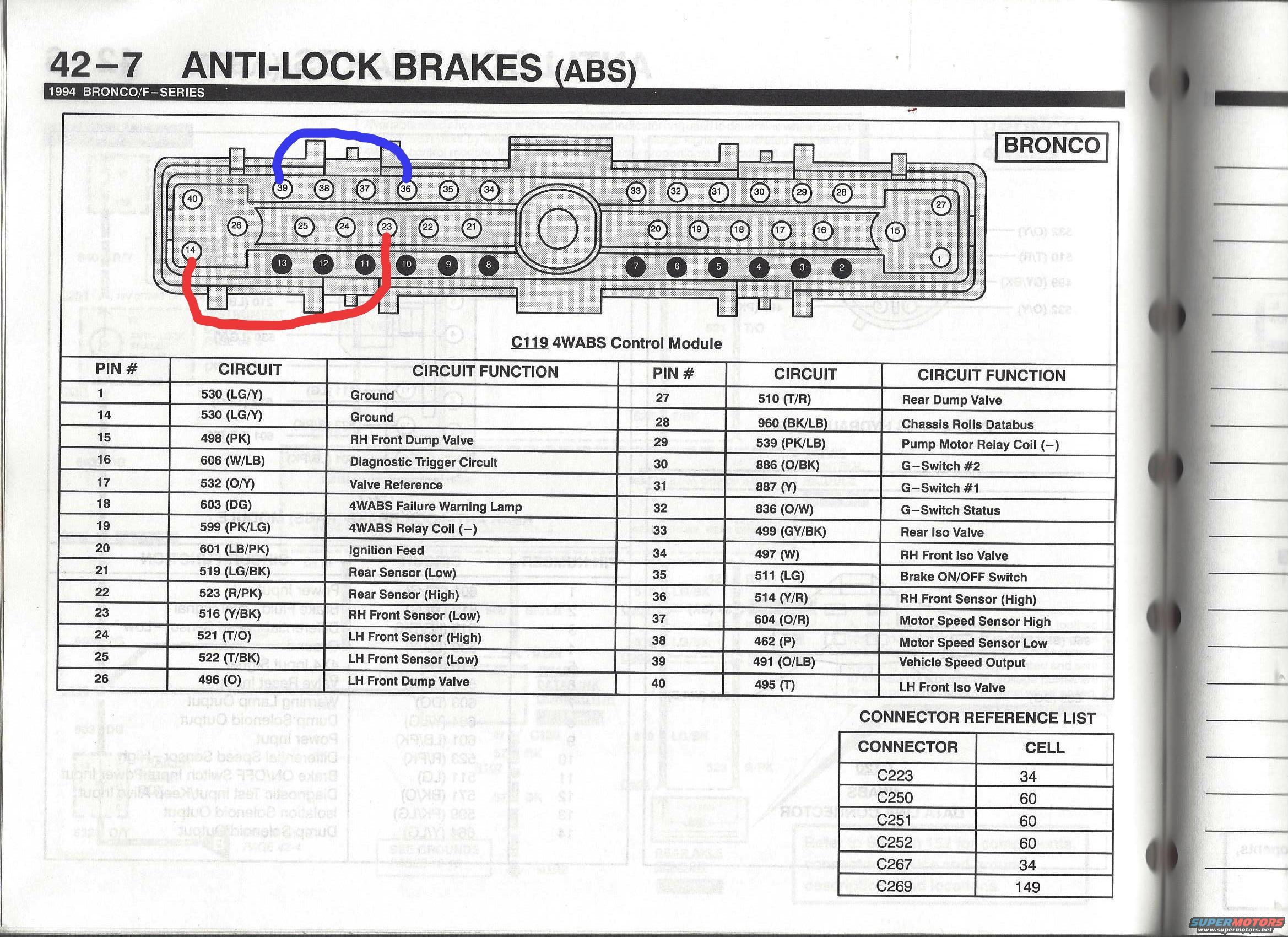
1994 Ford Bronco 4WABS Control Module C119 Connector Pinout - ABS Wiring Diagram
Reference · 1992-1996 BroncoAll 411 wiring diagrams
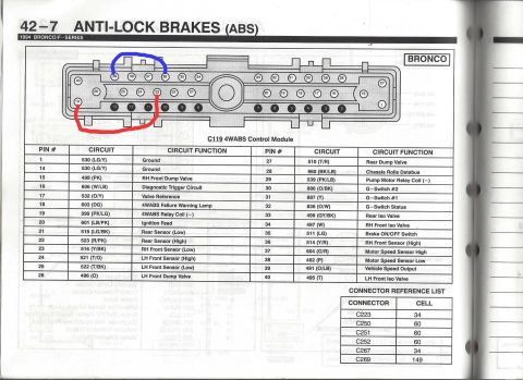
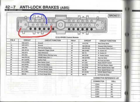
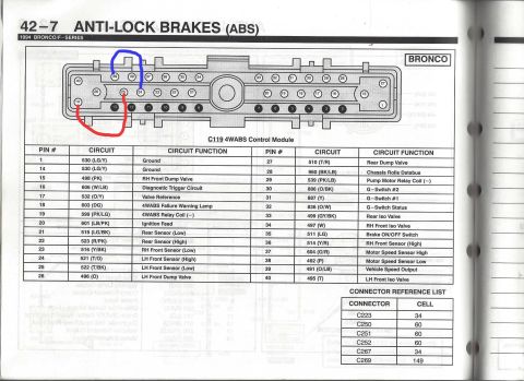
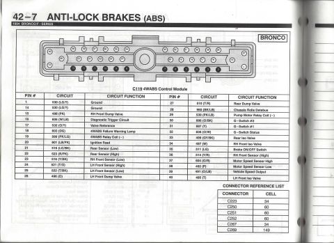
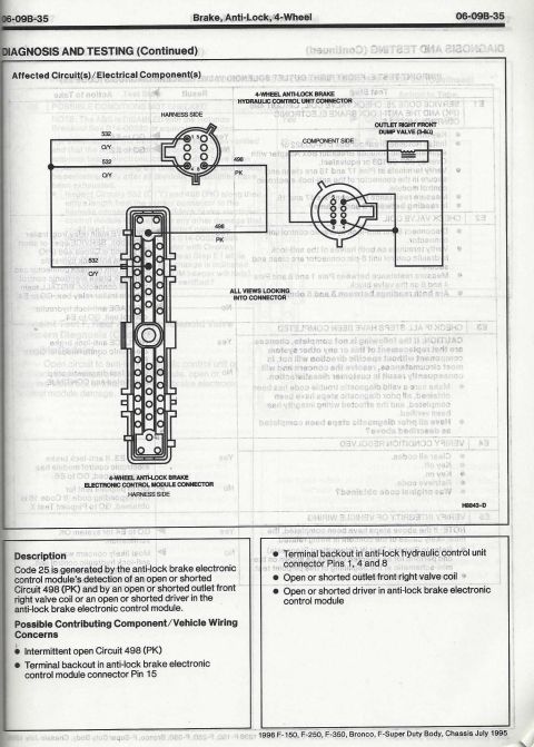

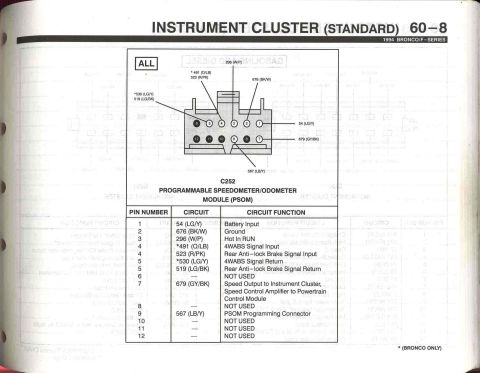
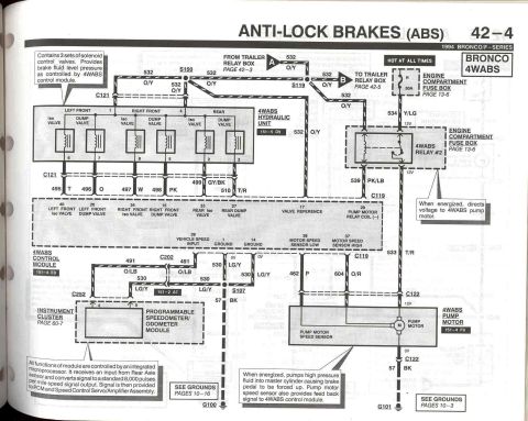
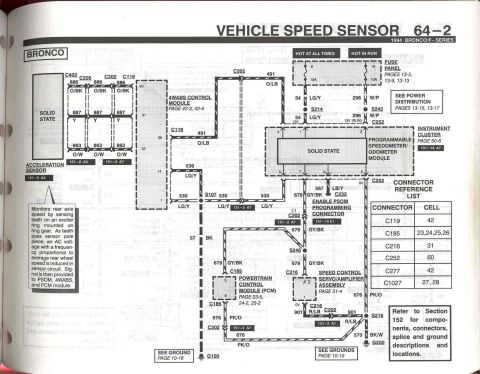






4WABS anti-lock brake control module connector C119 pinout (1994 Bronco/F-Series), annotated; 40-pin table of circuit numbers, wire colors and functions.
Part of 1992-1996 Ford Bronco Wiring Diagrams
This is page 42-7 from the 1994 Ford Bronco/F-Series Electrical & Vacuum Troubleshooting Manual (EVTM), covering the Anti-Lock Brakes (ABS) system. The page shows the C119 connector for the 4WABS (four-wheel anti-lock brake system) Control Module on the Bronco, with a physical pin-position diagram of the 40-pin connector and a complete pinout table. For each pin, the table lists the circuit number, wire color code, and circuit function, for example, pins 1 and 14 are grounds on circuit 530 (LG/Y), pin 20 is the ignition feed on 601 (LB/PK), pins 21-25 and 36 are the rear, RH front, and LH front wheel speed sensor high/low circuits, and pins 15, 26, 27, 33, 34, and 40 are the dump and isolation valve circuits. Other pins cover the 4WABS failure warning lamp, relay coils, G-switches, motor speed sensor, vehicle speed output, and diagnostic trigger. A connector reference list maps connectors C223, C250, C251, C252, C267, and C269 to their EVTM cell numbers. The scan includes hand-drawn red and blue marks highlighting certain pin groups on the connector diagram. Useful for diagnosing 4WABS wiring, sensor, and valve circuit issues.
Is this accurate? Sign in to help verify it.
Frequently asked questions
- What connector is shown for the 1994 Bronco 4WABS control module?
- Connector C119, a 40-pin connector for the 4WABS Control Module, with a pin-position diagram and full pinout table.
- Which pins on the C119 connector are grounds?
- Pins 1 and 14, both circuit 530 with a light green/yellow (LG/Y) wire.
- What pin is the ignition feed to the 4WABS module?
- Pin 20, circuit 601 with a light blue/pink (LB/PK) wire.
- Which pins carry the wheel speed sensor signals?
- Rear sensor: pin 21 low (519 LG/BK) and pin 22 high (523 R/PK). RH front: pin 23 low (516 Y/BK) and pin 36 high (514 Y/R). LH front: pin 24 high (521 T/O) and pin 25 low (522 T/BK).
- What circuit drives the 4WABS failure warning lamp?
- Pin 18, circuit 603 with a dark green (DG) wire.






No comments yet.