Home/
Registry/
Ford/
Bronco/
1992-1996/
1996 Ford Bronco/
Photo
supermotors.net/registry/media/898844
1996 Ford Bronco/F-150 Overhead Console Compass Temp Display Connector Pinout

Reference · 1992-1996 BroncoAll 15 fuse & relay charts
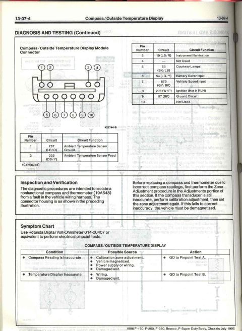



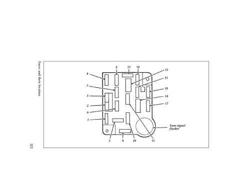
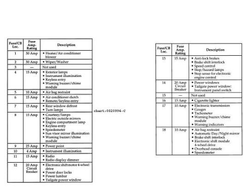
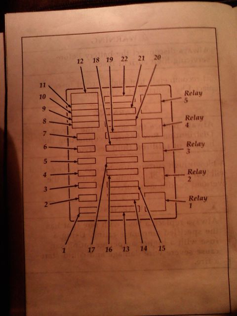
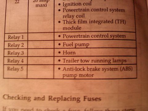







Ford service page (13-07-4) for the compass/outside-temperature display: connector pin-to-circuit tables (ignition pin 9, VSS pin 7, ambient sensor feed) plus symptom chart and demag note.
Part of 1992-1996 Ford Bronco Fuse & Relay Charts
This is page 13-07-4 from the 1996 Ford F-150/F-250/F-350/Bronco/F-Super Duty Body & Chassis service manual (dated July 1995), covering Diagnosis and Testing of the Compass/Outside Temperature Display in the overhead console. The page shows an illustration of the display module's 10-pin connector (illustration K22744-B) along with two pinout tables listing all ten pins, their circuit numbers, wire colors, and functions: pin 1 (767 LB/O, ambient temperature sensor ground), pin 2 (233 DB/Y, ambient temperature sensor feed), pin 3 (19 LB/R, instrument illumination), pin 5 (53 BK/LB, courtesy lamps), pin 6 (54 LG/Y, battery saver input), pin 7 (679 GY/BK, vehicle speed input), pin 8 (296 W/P, ignition hot in RUN), pin 9 (57 BK, ground), and pins 4 and 10 not used. The Inspection and Verification section explains diagnostics isolate a bad compass/thermometer unit (19A548) from harness faults, and instructs performing Zone Adjustment and calibration adjustment before replacement, with demagnetizing as a last resort. A Symptom Chart directs troubleshooting: inaccurate compass readings go to Pinpoint Test A; inaccurate temperature display goes to Pinpoint Test B, using Rotunda Digital Volt-Ohmmeter 014-00407 or equivalent.
Is this accurate? Sign in to help verify it.
Frequently asked questions
- What is the connector pinout for the 1996 Ford Bronco/F-150 compass/outside temperature display module?
- Pin 1: circuit 767 (LB/O) ambient temperature sensor ground; Pin 2: 233 (DB/Y) ambient temperature sensor feed; Pin 3: 19 (LB/R) instrument illumination; Pin 4: not used; Pin 5: 53 (BK/LB) courtesy lamps; Pin 6: 54 (LG/Y) battery saver input; Pin 7: 679 (GY/BK) vehicle speed input; Pin 8: 296 (W/P) ignition (hot in RUN); Pin 9: 57 (BK) ground circuit; Pin 10: not used.
- What should I do before replacing the compass due to inaccurate readings?
- First perform the Zone Adjustment procedure in the Adjustments portion of the section. If the compass transducer is still inaccurate, perform calibration adjustment, then set the zone adjustment again. If this fails, the vehicle must be demagnetized.
- What tool does Ford specify for the electrical pinpoint tests?
- Rotunda Digital Volt-Ohmmeter 014-00407 or equivalent.
- Which pinpoint test covers an inaccurate temperature display?
- Per the symptom chart, if the temperature display is inaccurate (possible sources: wiring or a damaged unit), GO to Pinpoint Test B. Inaccurate compass readings go to Pinpoint Test A.
- Which wire feeds the ambient temperature sensor?
- Circuit 233 (DB/Y) on pin 2 is the ambient temperature sensor feed; circuit 767 (LB/O) on pin 1 is the sensor ground.






No comments yet.