Home/
Registry/
Ford/
Bronco/
1992-1996/
1996 Ford Bronco/
Photo
supermotors.net/registry/media/1130956
Ford 5.0L / 5.8L HO Firing Order Diagram - Spark Plug Wire Routing & Timing
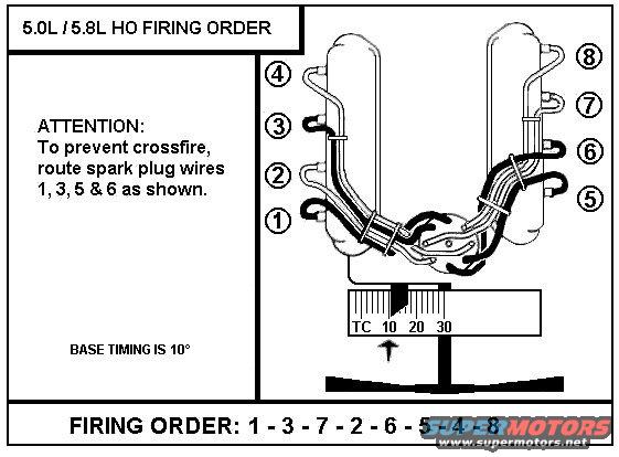
Ford 5.0L/5.8L HO firing order schematic 1-3-7-2-6-5-4-8 showing spark plug wire routing to prevent crossfire with base timing 10 degrees.
This schematic diagram illustrates the firing order and spark plug wire routing for Ford 5.0L and 5.8L HO (High Output) V8 engines. The firing order is clearly stated as 1-3-7-2-6-5-4-8. The diagram shows a top-down view of the engine with both cylinder banks: cylinders 1 through 4 on one side and 5 through 8 on the other, with circled numbers indicating each cylinder's spark plug wire position. An attention note warns that to prevent crossfire, spark plug wires 1, 3, 5 & 6 must be routed as shown in the drawing, where the wires are depicted crossing and bundled in specific paths from the distributor to each cylinder. The document also specifies that base ignition timing is 10 degrees, illustrated with a timing scale (TC, 10, 20, 30) and an arrow pointing to the 10-degree mark. A reader can learn the correct firing order for these engines, the proper physical routing of the plug wires to avoid induction crossfire between adjacent cylinders, and the factory base timing setting. The document itself contains no year, model, or part number information beyond the engine displacements.
Is this accurate? Sign in to help verify it.
Frequently asked questions
- What is the firing order for the Ford 5.0L / 5.8L HO engine?
- The firing order is 1-3-7-2-6-5-4-8.
- What is the base ignition timing for the 5.0L/5.8L HO?
- Base timing is 10 degrees, as shown by the arrow at the 10 mark on the timing scale (TC 10 20 30).
- Which spark plug wires need special routing to prevent crossfire?
- Spark plug wires 1, 3, 5 & 6 must be routed as shown in the diagram to prevent crossfire.
- How are the cylinders numbered on this engine?
- The diagram shows cylinders 1-4 on one bank (numbered 1 at the front to 4 at the rear) and cylinders 5-8 on the other bank (5 at the front to 8 at the rear).
Comments
More from this build












No comments yet.