Home/
Registry/
Ford/
LTD Crown Victoria/
1983-1991/
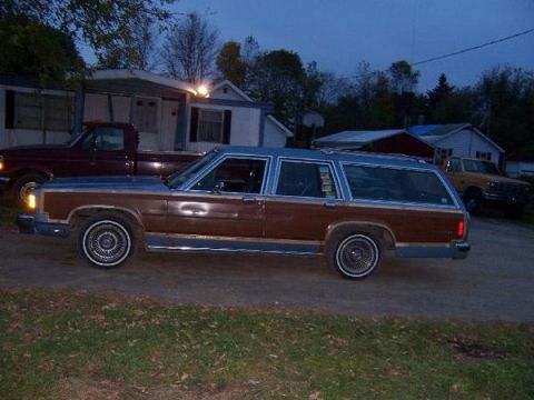
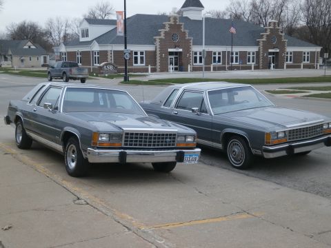
“babycakes”/
Photo
supermotors.net/registry/media/205175
1985 Ford LTD Crown Victoria Tripminder Circuit & Component Locations - EVTM p78
Reference · 1983-1991 LTD Crown VictoriaAll 12 manual pages
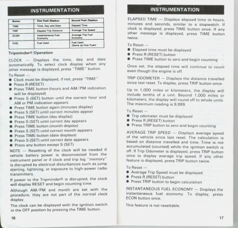
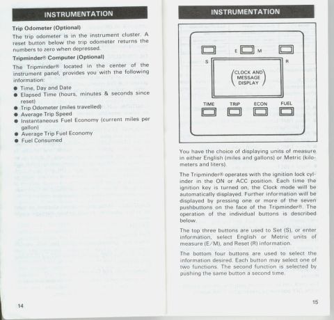
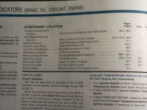

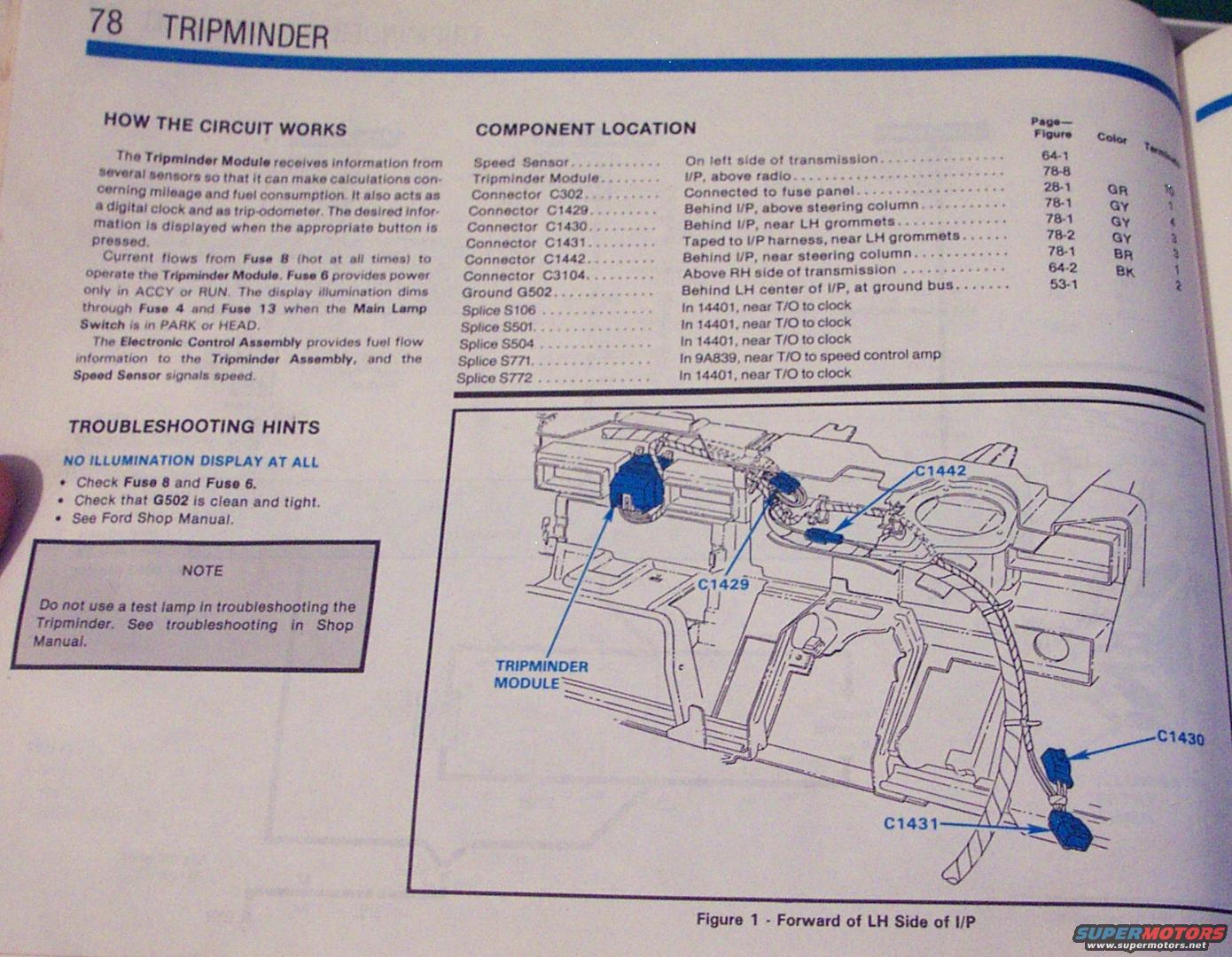
Service manual page describing how the Tripminder circuit works, with component-location list and an underdash routing diagram.
Part of 1983-1991 Ford LTD Crown Victoria Manual Pages
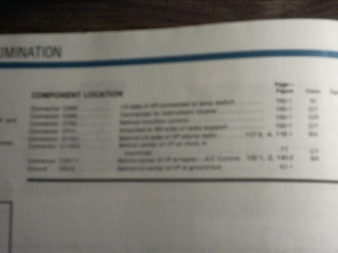
This is page 78 of a Ford Electrical and Vacuum Troubleshooting Manual (EVTM), covering the Tripminder system. The 'How the Circuit Works' section explains that the Tripminder Module receives input from several sensors to calculate mileage and fuel consumption and also functions as a digital clock and trip-odometer. Fuse 8 (hot at all times) powers the module, Fuse 6 supplies power in ACCY or RUN, and display illumination dims through Fuse 4 and Fuse 13 when the Main Lamp Switch is in PARK or HEAD. The Electronic Control Assembly supplies fuel flow data and the Speed Sensor signals speed. Troubleshooting hints for 'no illumination display at all' direct the reader to check Fuses 8 and 6 and ground G502, with a note warning against using a test lamp on the Tripminder. A component location table lists the Speed Sensor, Tripminder Module, connectors C302, C1429, C1430, C1431, C1442, C3104, ground G502, and splices S106, S501, S504, S771, and S772, with their physical locations, page/figure references, connector colors, and terminal counts. Figure 1 illustrates the area forward of the LH side of the instrument panel, showing the Tripminder Module and connectors C1429, C1442, C1430, and C1431.
Is this accurate? Sign in to help verify it.
Frequently asked questions
- Which fuses power the Tripminder Module?
- Fuse 8 (hot at all times) operates the Tripminder Module, and Fuse 6 provides power only in ACCY or RUN. Display illumination dims through Fuse 4 and Fuse 13 when the Main Lamp Switch is in PARK or HEAD.
- What should I check if the Tripminder display has no illumination at all?
- Check Fuse 8 and Fuse 6, check that ground G502 is clean and tight, and see the Ford Shop Manual.
- Where is the Tripminder Module located?
- In the instrument panel (I/P), above the radio.
- Where is the Speed Sensor for the Tripminder located?
- On the left side of the transmission.
- Can I use a test lamp to troubleshoot the Tripminder?
- No. The manual notes: 'Do not use a test lamp in troubleshooting the Tripminder. See troubleshooting in Shop Manual.'

No comments yet.