Home/
Registry/
Ford/
LTD Crown Victoria/
1983-1991/
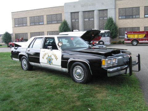
1985 Ford LTD Crown Victoria/
Photo
supermotors.net/registry/media/504719
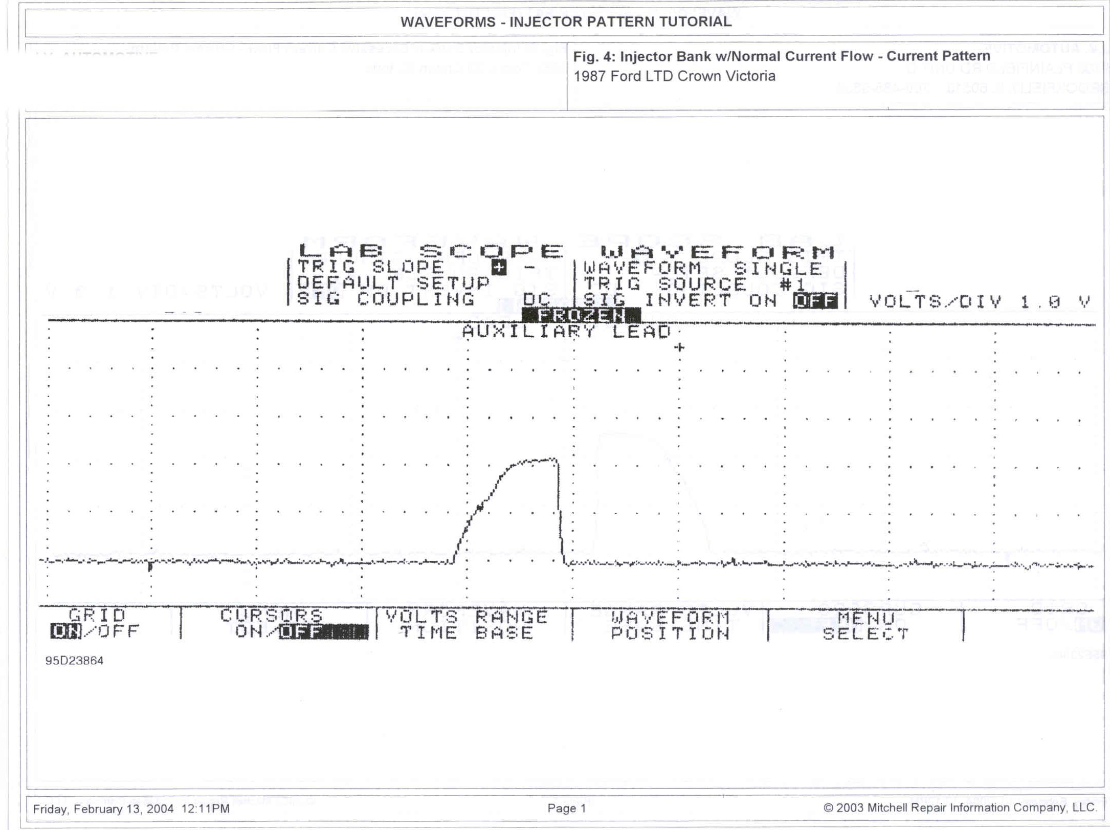
1987 Ford LTD Crown Victoria Injector Bank Normal Current Waveform - Lab Scope
Reference · 1983-1991 LTD Crown VictoriaAll 12 manual pages
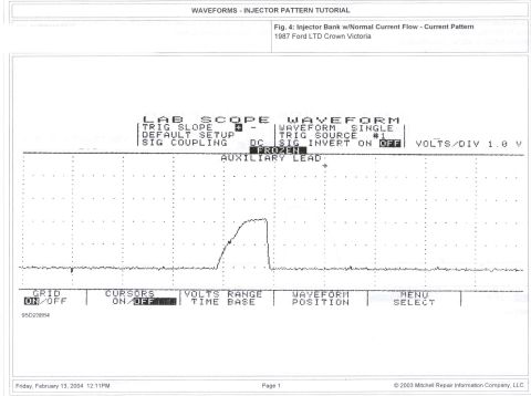
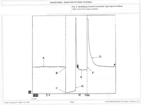
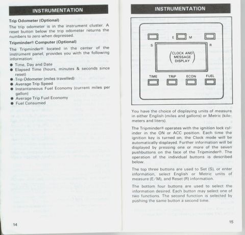
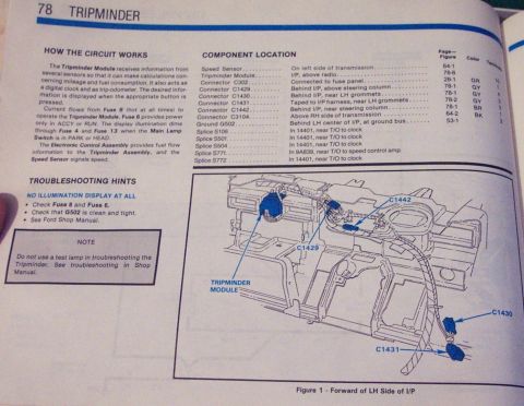
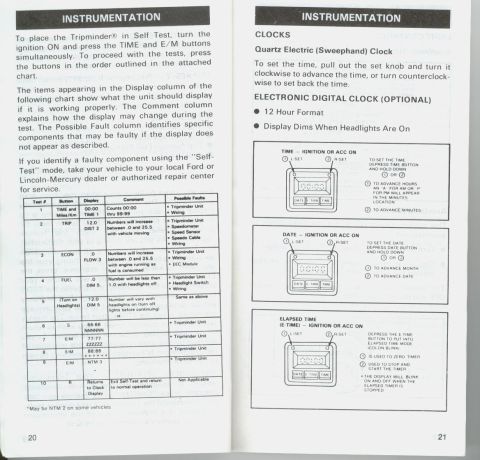

Scanned Mitchell service manual page illustrating a normal fuel-injector current-flow lab scope waveform for a 1987 Ford Crown Victoria.
Part of 1983-1991 Ford LTD Crown Victoria Manual Pages
This document is a single page from a Mitchell Repair Information 'Waveforms - Injector Pattern Tutorial,' showing Fig. 4: 'Injector Bank w/Normal Current Flow - Current Pattern,' captured on a 1987 Ford LTD Crown Victoria. The page reproduces a lab scope (oscilloscope) screen capture of a fuel injector bank's current waveform under normal operating conditions. The scope settings shown on screen include: trigger slope positive, waveform mode SINGLE, trigger source #1, signal coupling DC, signal invert OFF, and a vertical scale of 1.0 volt per division, with the trace measured via an auxiliary (amp probe) lead and the display frozen. The waveform itself shows a flat baseline followed by a single ramped current hump that rises, plateaus briefly, and drops sharply back to baseline, the characteristic shape of normal injector bank current draw. On-screen soft-key menus (GRID ON/OFF, CURSORS ON/OFF, VOLTS RANGE/TIME BASE, WAVEFORM POSITION, MENU SELECT) are visible. The figure carries reference number 95D23864 and was printed February 13, 2004, from 2003 Mitchell Repair Information Company material. A reader can use this as a known-good comparison waveform when diagnosing bank-fired fuel injector circuits with a lab scope and current probe.
Is this accurate? Sign in to help verify it.
Frequently asked questions
- What does this waveform show?
- It shows Fig. 4, an injector bank current pattern with normal current flow, captured with a lab scope on a 1987 Ford LTD Crown Victoria using an auxiliary lead.
- What scope settings were used to capture this injector current pattern?
- Trigger slope positive, waveform mode SINGLE, trigger source #1, signal coupling DC, signal invert OFF, and 1.0 volt per division, with the display frozen.
- What vehicle was this normal injector current waveform recorded on?
- A 1987 Ford LTD Crown Victoria.
- What is the source of this document?
- It is page 1 of a 'Waveforms - Injector Pattern Tutorial' from Mitchell Repair Information Company, LLC (© 2003), printed Friday, February 13, 2004, figure reference 95D23864.



No comments yet.