Home/
Registry/
Ford/
LTD Crown Victoria/
1983-1991/
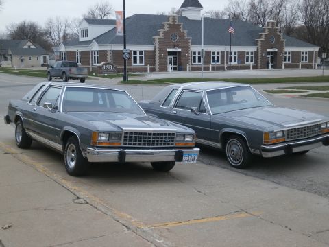
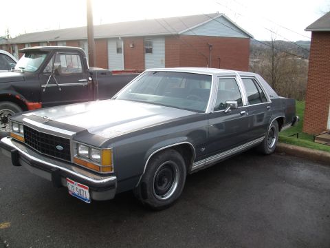
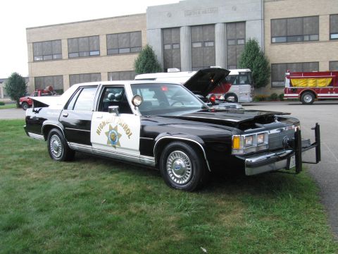
1985 Ford LTD Crown Victoria/
Photo
supermotors.net/registry/media/504718
1987 Ford LTD Crown Victoria Injector Bank Excessive Current Waveform - Fig. 5
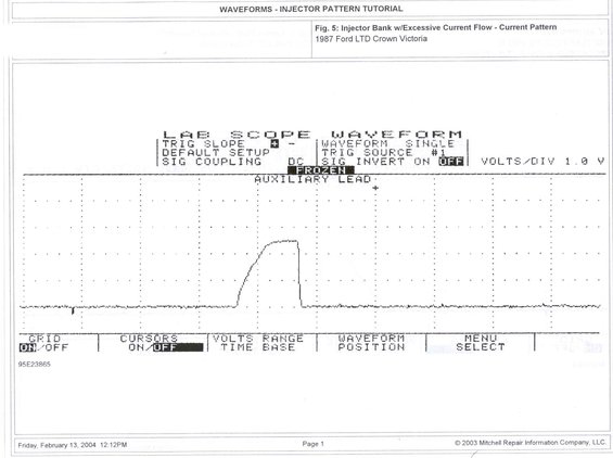
Service manual injector-pattern tutorial page showing a lab scope current waveform and scope settings.
Part of 1983-1991 Ford LTD Crown Victoria Manual Pages
This document is a page from a Mitchell Repair Information waveform tutorial titled "Waveforms - Injector Pattern Tutorial." It presents Fig. 5, a lab scope screen capture labeled "Injector Bank w/Excessive Current Flow - Current Pattern," recorded on a 1987 Ford LTD Crown Victoria. The oscilloscope settings shown on screen include a positive trigger slope, single waveform mode, trigger source #1, DC signal coupling, signal invert off, and a scale of 1.0 volts per division, with the display frozen and captured through the auxiliary lead. The waveform itself shows a flat baseline interrupted by a single injector bank current pulse that ramps up to a plateau (roughly three divisions high at 1.0 V/div) before dropping sharply back to baseline, illustrating what an excessive current flow pattern looks like for a bank-fired injector circuit. Soft-key menu labels for grid on/off, cursors, volts range/time base, waveform position, and menu select are visible at the bottom. The page carries reference number 95E23865, was printed Friday, February 13, 2004 at 12:12 PM, and is copyright 2003 Mitchell Repair Information Company, LLC. It is part of a set of injector pattern tutorial waveform examples useful for diagnosing fuel injector driver circuits.
Is this accurate? Sign in to help verify it.
Frequently asked questions
- What vehicle was this injector current waveform captured on?
- The figure caption states it was captured on a 1987 Ford LTD Crown Victoria.
- What does this waveform show?
- It shows Fig. 5: an injector bank with excessive current flow, displayed as a current pattern on a lab scope, a single pulse ramping to a plateau before dropping sharply back to baseline.
- What scope settings were used for this capture?
- Trigger slope positive, single waveform mode, trigger source #1, default setup, DC signal coupling, signal invert off, and 1.0 volts per division, captured on the auxiliary lead with the display frozen.
- Who published this document and when?
- It is copyright 2003 Mitchell Repair Information Company, LLC, and the page was printed Friday, February 13, 2004 at 12:12 PM.
Comments
More from this build




No comments yet.