Home/
Registry/
Ford/
Taurus/
1992-1995/
1992 Ford Taurus/
Photo
supermotors.net/registry/media/225416
Basic 12V Switched Accessory Wiring Diagram - Switch, Accessory & Ground

Reference · 1992-1995 TaurusAll 37 wiring diagrams


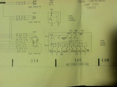
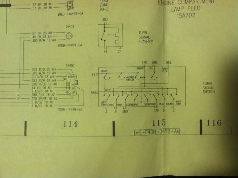
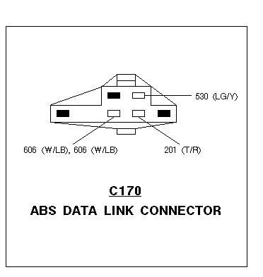
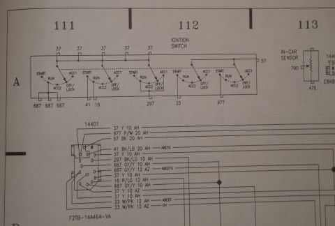



Wiring diagram showing an accessory connected through a switch to a +12V source with ground.
Part of 1992-1995 Ford Taurus Wiring Diagrams
This is a simple hand-drawn wiring schematic showing how to wire a basic 12-volt automotive accessory with a switch. The drawing depicts an accessory (represented by a yellow bulb-like symbol) with one terminal connected to chassis ground (shown with a standard ground symbol in black) and the other terminal wired in red through an in-line switch to a +12V power source. The switch is drawn in the open position between the accessory and the +12V supply, illustrating that the switch interrupts the power (hot) side of the circuit rather than the ground side. There are no fuse ratings, wire gauges, wire color codes, part numbers, connector details, or vehicle-specific information shown. The diagram is generic and educational rather than model-specific; it appears to be part of a set of basic electrical tutorial drawings (companion files in the album are named parallel.gif and series.gif, suggesting a series on fundamental circuit wiring). A reader can learn the basic layout of a switched 12V accessory circuit: power source → switch → accessory → ground. It applies equally to any 12-volt vehicle, including the uploader's claimed 1992 Ford Taurus, though nothing in the drawing ties it to any specific year, make, or model.
Is this accurate? Sign in to help verify it.
Frequently asked questions
- How do I wire a 12V accessory with a switch?
- Per the diagram, connect one terminal of the accessory to ground, and run the other terminal through a switch to the +12V power source.
- Should the switch go on the power side or ground side of the accessory?
- The diagram shows the switch placed between the +12V source and the accessory, i.e., on the power (hot) side; the accessory's other terminal goes directly to ground.
- Does this diagram specify a fuse or wire gauge?
- No. The drawing shows only the accessory, switch, +12V source, and ground; no fuse, amperage, or wire gauge is indicated.
- Is this diagram specific to a particular vehicle?
- No. It is a generic hand-drawn schematic labeled only ACCESSORY, SWITCH, and +12v, with no vehicle year, make, or model shown.



No comments yet.