Nissan Automatic Transmission Disassembly AT-19 - Governor Shaft & Exploded View
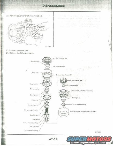
Service manual page AT-19 showing an exploded breakdown of automatic transaxle internal gear and clutch components.
This is page AT-19 from a service manual's automatic transmission Disassembly section. It continues a numbered disassembly procedure: step 22 instructs removal of the governor shaft retaining bolt (with an illustration, figure SAT269, showing a wrench on the transmission case), step 23 says to pull out the governor shaft, and step 24 lists the parts to remove next. The bulk of the page is an exploded parts diagram (figure SAT655) showing the internal geartrain and clutch components in disassembly order, with callouts identifying: rear internal gear, bearing races, thrust washers, snap rings, one-way clutch assembly, front internal gear, rear carrier, forward clutch (Rear) assembly, thrust needle bearings, connecting shell, sun gear, front carrier assembly, and high-reverse clutch (Front) assembly. A reader can use this page to understand the order and identity of the internal transmission components removed after the governor shaft, which is useful for teardown and reassembly reference. A short paragraph at the top right of the page is too faded to read reliably. The page itself carries no year, make, or model identification beyond the AT-19 page number and SAT-prefixed figure codes typical of Nissan automatic transmission manuals.
Is this accurate? Sign in to help verify it.
Frequently asked questions
- How do you remove the governor shaft during transmission disassembly?
- Per steps 22-23, remove the governor shaft retaining bolt (shown in figure SAT269), then pull out the governor shaft.
- What parts are removed after pulling out the governor shaft?
- Step 24's exploded diagram shows: rear internal gear, bearing races, thrust washers, snap rings, one-way clutch assembly, front internal gear, rear carrier, forward clutch (Rear) assembly, thrust needle bearings, connecting shell, sun gear, front carrier assembly, and high-reverse clutch (Front) assembly.
- Which clutch assemblies appear in the exploded view on page AT-19?
- The one-way clutch assembly, the forward clutch (Rear) assembly, and the high-reverse clutch (Front) assembly.
- What figure numbers are referenced on this page?
- SAT269 (governor shaft retaining bolt removal illustration) and SAT655 (exploded parts diagram).
Comments
More from this build











No comments yet.