Home/
Registry/
Ford/
Bronco/
1992-1996/
1994 Ford Bronco/
Photo
supermotors.net/registry/media/253193
1994 Ford Bronco/F-Series Behind Instrument Panel Component Location Diagram
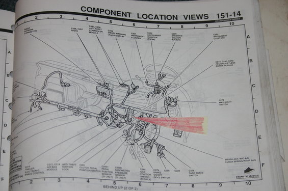
Service manual component-location-views page showing connector and module locations behind the instrument panel.
Part of 1992-1996 Ford Bronco Manual Pages
This is page 151-14 from the 1994 Ford Bronco/F-Series electrical/vacuum troubleshooting manual (EVTM), titled "Component Location Views: Behind I/P (2 of 2)." It presents an exploded line drawing of the wiring harness routed behind the instrument panel, with numbered callouts identifying electrical connectors and components. Identified items include the radio antenna connector, radio connectors C258/C257, anti-theft controller module (C237, C238), diesel warning lamps display (C264), instrument cluster connectors C251, C252 (PSOM), and C250, the steering column air bag connector C226, remote keyless entry module (C240, C241, C242), main light switch (C273), trailer electronic brake control (C210), air bag module (C217, C218), anti-theft ignition lock, clutch pedal position switch (C261), pedal position sensor C2001 and barometric pressure sensor C2000 (diesel only), idle position switch C244 (DI only), brake on/off (BOO) switch C279, park brake switch C276, plus connectors C200 and C229, and the clock-spring brush assembly for air-bag equipped trucks. A grid reference system (columns 1-10, rows A-F) and a "Front of Vehicle" arrow aid in locating parts. Readers can use this page to physically locate behind-dash connectors and modules on a 1994 Bronco or F-Series truck.
Is this accurate? Sign in to help verify it.
Frequently asked questions
- What page and vehicles does this component location view cover?
- It is page 151-14, labeled 1994 Bronco/F-Series, showing component location views behind the instrument panel (Behind I/P, 2 of 2).
- Which connectors go to the instrument cluster on the 1994 Bronco/F-Series?
- The diagram identifies C251 instrument cluster, C252 instrument cluster (PSOM), and C250 instrument cluster connectors.
- Where is the remote keyless entry module connector shown?
- Connectors C240, C241, and C242 for the remote keyless entry module are called out behind the instrument panel on the right side of the diagram.
- What is connector C279?
- C279 is the brake on/off (BOO) switch connector, located near the pedal area behind the instrument panel.
- Which sensors on this page are marked as diesel (DI) only?
- C2001 pedal position sensor, C2000 barometric pressure sensor, and C244 idle position switch are all marked (DI ONLY); a C264 diesel warning lamps display connector is also shown.
Comments
More from this build








No comments yet.