Home/
Registry/
Ford/
Bronco/
1992-1996/
1994 Ford Bronco/
Photo
supermotors.net/registry/media/264222
Ford Engine Compartment Connector Location Diagram - PCM, MAF, IAT, SPOUT (EVTM)

Reference · 1992-1996 BroncoAll 101 manual pages
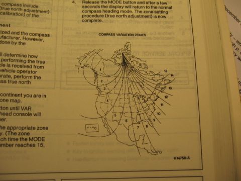

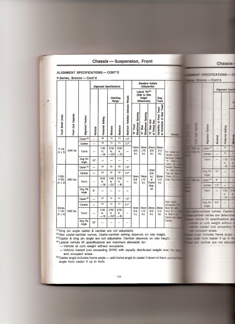

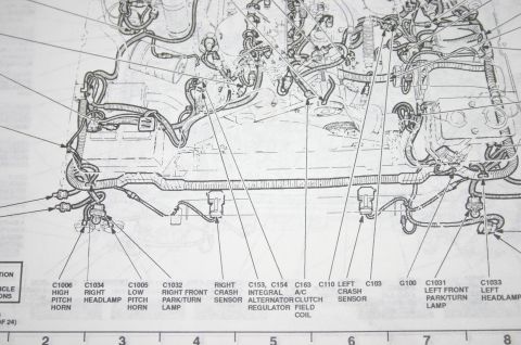
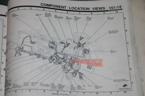

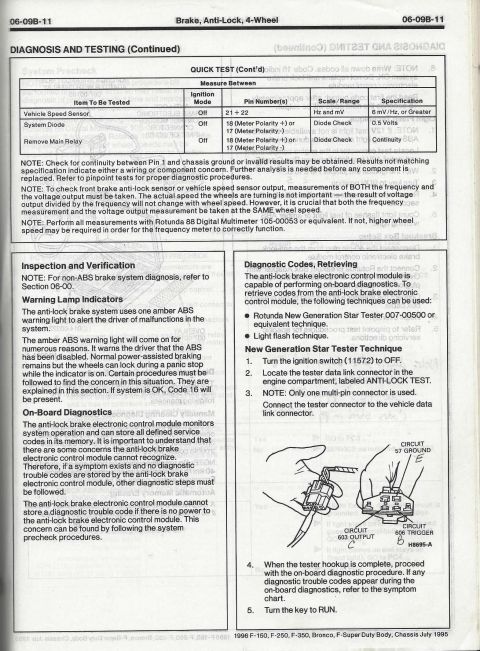
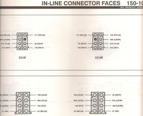
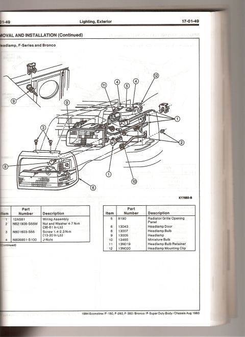
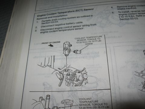
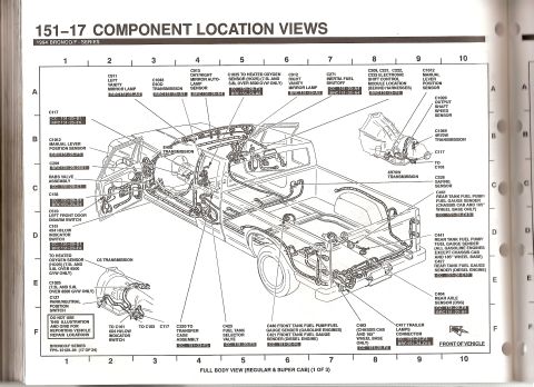






Service manual connector-location view of the engine bay harness with headlamp, horn, and crash-sensor callouts.
Part of 1992-1996 Ford Bronco Manual Pages
This is a scanned page from a Ford electrical/vacuum troubleshooting manual (EVTM-style component location view) showing a detailed line-art illustration of an engine compartment with leader lines pointing to electrical components and connectors. A highlighted reference reads "LIGHTNING 151-6-A5." Labeled items include the ignition coil, radio capacitor, C120 4WABS (four-wheel anti-lock brake system) data link connector, C198/C199 VIP data link connector, C1021 ignition control module, C185 powertrain control module (PCM), C1019 SPOUT check connector with C101, C164 intake air temperature (IAT) sensor, C130 mass air flow (MAF) sensor noted for the 5.0L engine, C1016 power steering pressure switch, and C119. Grid coordinate letters A through E run along the page edge for locating components in the diagram. A reader can use this page to physically locate these connectors, sensors, and modules in the engine bay when diagnosing engine management, ignition, or ABS wiring issues, and to cross-reference connector numbers (C-numbers) used elsewhere in the wiring manual. The page itself is undated and does not state a model year, though the "LIGHTNING" reference indicates applicability to the Ford F-150 Lightning variant.
Is this accurate? Sign in to help verify it.
Frequently asked questions
- Where is the SPOUT check connector identified in this diagram?
- The diagram labels C1019 as the SPOUT check connector, shown together with connector C101, located in the engine compartment near the center of the illustration.
- What connector number is the powertrain control module (PCM)?
- The PCM is identified as connector C185 in this component location view.
- Which engine is the MAF sensor callout for?
- The mass air flow (MAF) sensor, connector C130, is labeled specifically for the 5.0L engine.
- What are C198 and C199 on this page?
- C198 and C199 are labeled as the VIP data link connector.
- What is connector C1016?
- C1016 is labeled as the power steering pressure switch, shown near C119 in the engine compartment.






No comments yet.