Home/
Registry/
Ford/
Bronco/
1992-1996/
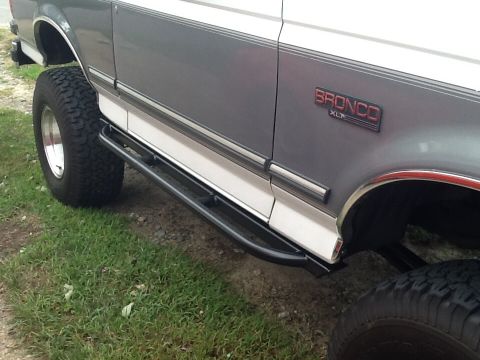
1994 Ford Bronco/
Photo
supermotors.net/registry/media/845020
1994 Ford Bronco/F-Series In-Line Connector Faces C213 Pinout Wiring Diagram
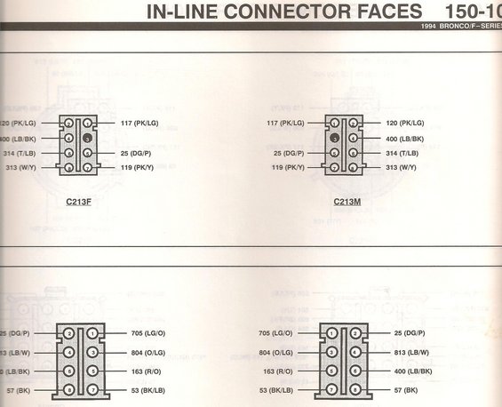
Ford 1994 Bronco/F-Series in-line connector face pinout diagram C213 with numbered pins and wire color codes.
Part of 1992-1996 Ford Bronco Wiring Diagrams
This is a scanned page from the 1994 Ford Bronco/F-Series factory wiring reference, section "In-Line Connector Faces" (page 150-10, partially cut off). It shows pin-out face views of in-line harness connectors, illustrating both the female (F) and male (M) sides of each mating pair. The upper pair is labeled C213F and C213M: an 8-cavity connector with pin 3 plugged (solid black, unused). Circuits shown are 117 (PK/LG), 120 (PK/LG), 400 (LB/BK), 25 (DG/P), 314 (T/LB), 119 (PK/Y), and 313 (W/Y). The lower pair (connector designation cut off at the bottom of the scan) is another 8-cavity connector carrying circuits 705 (LG/O), 25 (DG/P), 804 (O/LG), 813 (LB/W), 163 (R/O), 400 (LB/BK), 53 (BK/LB), and 57 (BK). Each callout gives the Ford circuit number followed by the wire color abbreviation in parentheses. A reader can use this page to identify which numbered cavity in connector C213 (and the second connector) carries which circuit and wire color, useful for tracing wiring, diagnosing open circuits, or back-probing at these in-line connectors on a 1994 Bronco or F-Series truck.
Is this accurate? Sign in to help verify it.
Frequently asked questions
- What vehicles does this connector face diagram apply to?
- The page header states it is for the 1994 Bronco/F-Series, from the 'In-Line Connector Faces' section (page 150-10, partially cut off).
- What circuits are in connector C213 on a 1994 Bronco/F-Series?
- C213 (shown as female C213F and male C213M) carries: pin 1-117 (PK/LG), pin 2-120 (PK/LG), pin 3, plugged/unused, pin 4-400 (LB/BK), pin 5-25 (DG/P), pin 6-314 (T/LB), pin 7-119 (PK/Y), pin 8-313 (W/Y).
- What wire color is circuit 400 in these connectors?
- Circuit 400 is shown as LB/BK (light blue/black) in both C213 and the lower connector on this page.
- Is pin 3 of connector C213 used?
- No: pin 3 is drawn as a solid black (plugged) cavity in both the C213F and C213M faces, with no circuit assigned.
- What circuits are in the second (lower) connector on this page?
- The lower 8-pin connector carries: 705 (LG/O), 25 (DG/P), 804 (O/LG), 813 (LB/W), 163 (R/O), 400 (LB/BK), 53 (BK/LB), and 57 (BK). Its connector designation is cut off at the bottom of the scan.
Comments
More from this build










No comments yet.