1978 Ford Bronco Hydraulic Brake System Exploded Parts Diagram - Part Numbers

Reference · 1992-1996 BroncoAll 169 exploded parts diagrams
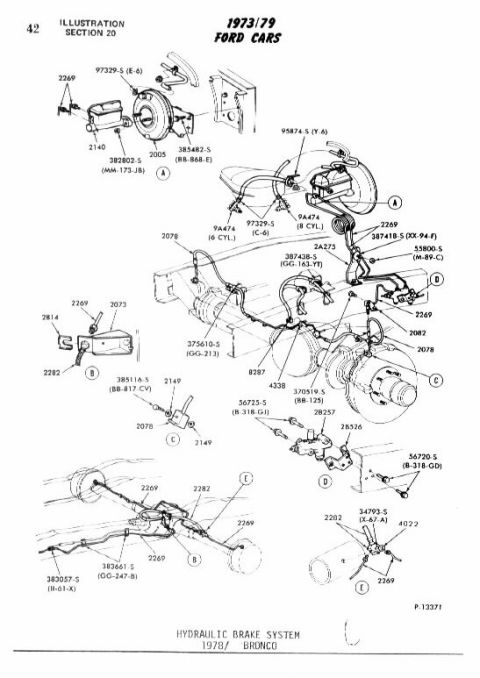
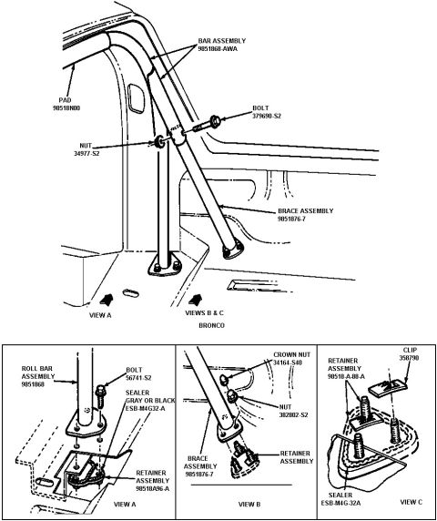
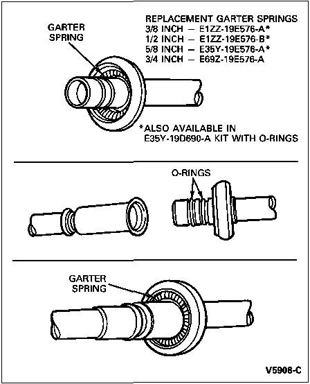
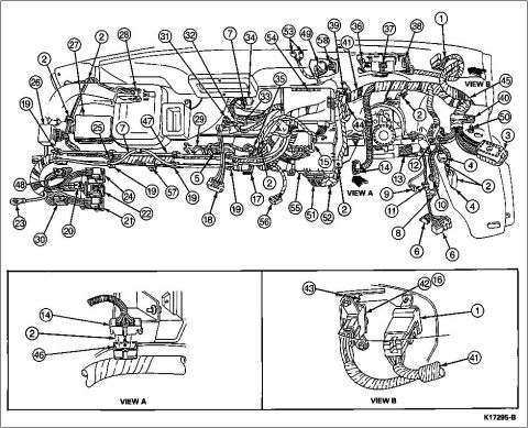
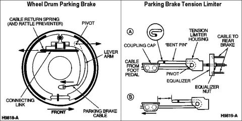







Exploded parts illustration of the 1973-79 Ford hydraulic brake system showing booster, lines and fittings with part numbers.
Part of 1992-1996 Ford Bronco Exploded Parts Diagrams
This is page 42 (Illustration Section 20) from a 1973-79 Ford Cars parts illustration catalog, showing the hydraulic brake system for the 1978 Ford Bronco (figure number P-13371). The exploded parts diagram illustrates the complete hydraulic brake plumbing: the master cylinder and vacuum brake booster assembly (with separate callouts for 6-cylinder and 8-cylinder vacuum hose part 9A474), brake lines and tubes routed along the frame and to the front and rear axles, brake hoses, distribution/proportioning valve, and related clips, brackets, clamps, and fasteners. Lettered detail views (A through E) enlarge the booster/master cylinder mounting, line-retaining brackets, valve assemblies, and the rear axle brake line junction. Each component carries a Ford base part number (e.g., 2140 master cylinder area, 2005, 2A275, 2078, 2269, 2282, 4338, 8287, 4022, 28257, 28526) and hardware/service part numbers with suffix codes (e.g., 382802-S MM-173-JB, 385482-S BB-868-E, 387418-S XX-94-F, 387438-S GG-163-YT, 375610-S GG-213, 385116-S BB-817-CV, 370519-S BB-125, 56725-S B-318-GJ, 56720-S B-318-GD, 383661-S GG-247-B, 383057-S II-61-X, 34793-S X-67-A). A reader can identify part numbers and physical routing/mounting locations for every hydraulic brake component on a 1978 Bronco.
This document covers 1973-1979 (figure captioned 1978/ Bronco, which may differ from this 1992 Ford Bronco.
Is this accurate? Sign in to help verify it.
Frequently asked questions
- What vehicle and system does this diagram cover?
- It shows the hydraulic brake system for the 1978 Ford Bronco, from a 1973/79 Ford Cars parts illustration catalog (Section 20, page 42, figure P-13371).
- Does the diagram distinguish between 6-cylinder and 8-cylinder parts?
- Yes. Part 9A474 (booster vacuum hose) is called out separately for 6 CYL. and 8 CYL. applications, and fastener 97329-S is shown with (E-6) and (C-6) codes.
- What base part numbers are shown for the master cylinder and booster area?
- Callouts in the master cylinder/booster views include 2140, 2005, 2269, plus hardware 97329-S (E-6), 382802-S (MM-173-JB), 385482-S (BB-868-E), 95874-S (Y-6), 387418-S (XX-94-F), and 55800-S (M-89-C).
- What part numbers appear for the rear axle brake lines?
- The rear axle views show 2269, 2282, 4022, 34793-S (X-67-A), 383661-S (GG-247-B), and 383057-S (II-61-X).
- What part numbers are shown for the brake valve details?
- View C shows 385116-S (BB-817-CV), 2149, and 2078; View D shows 28257, 28526, 56725-S (B-318-GJ), and 56720-S (B-318-GD).






No comments yet.