1992 Ford Bronco Dash Wiring Harness & Connector Locations Diagram (K17295-B)

Reference · 1992-1996 BroncoAll 169 exploded parts diagrams
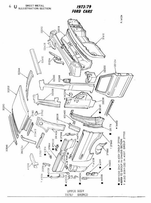
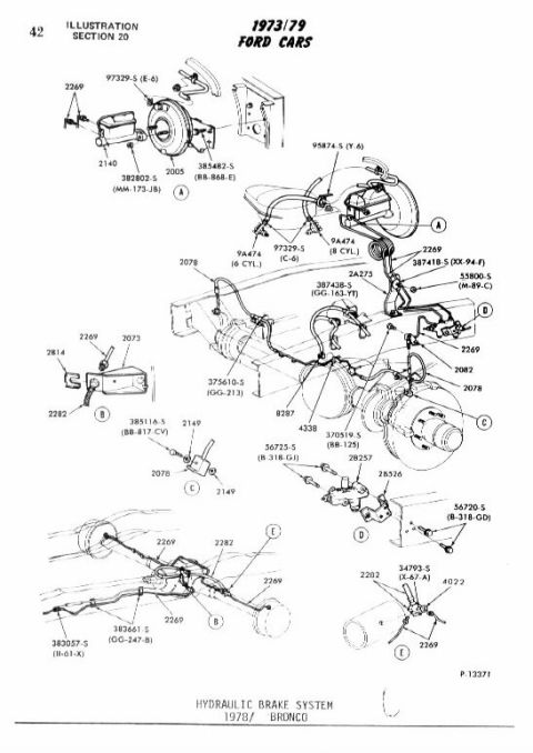
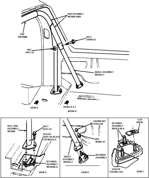
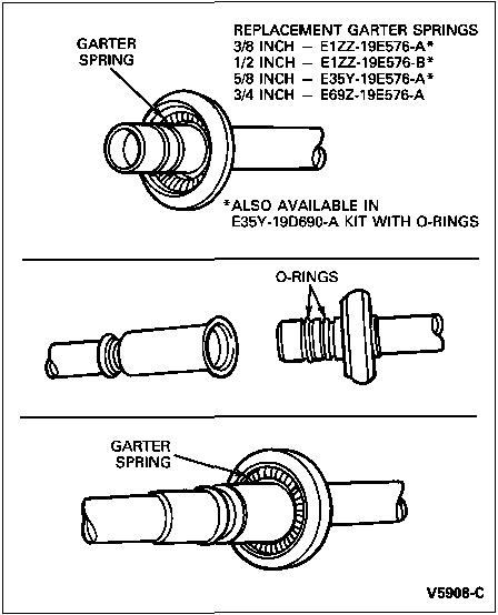
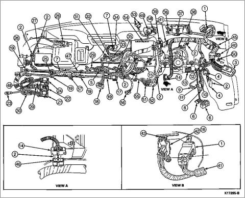
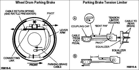
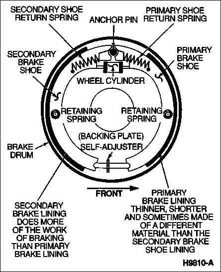
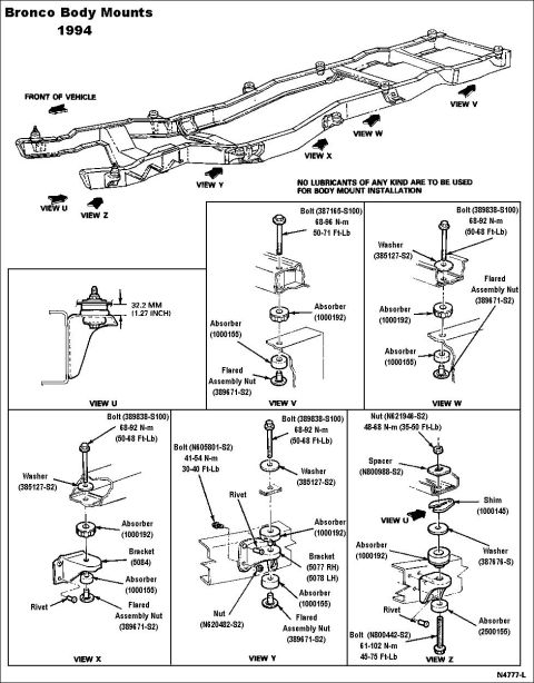


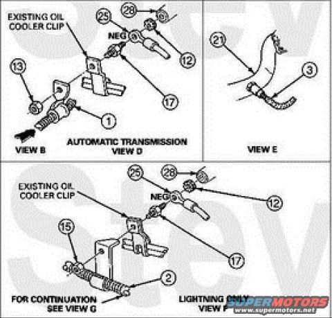

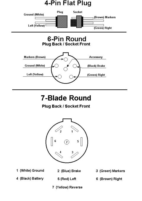
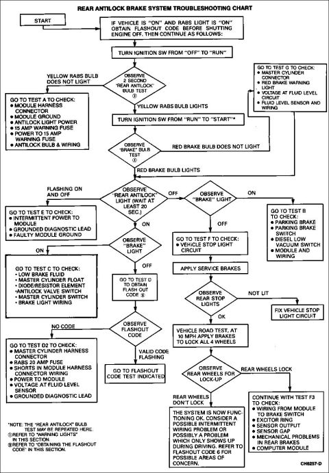
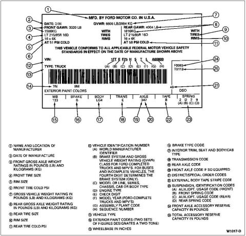
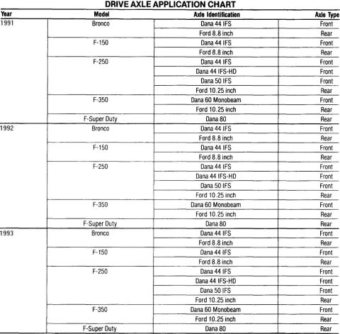
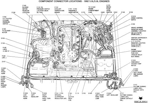
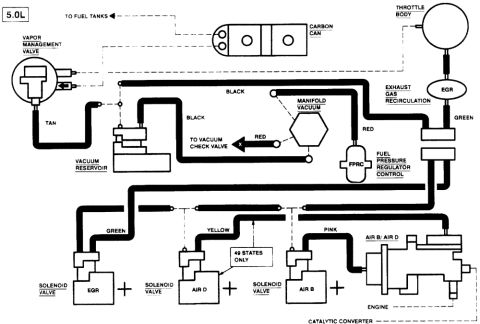
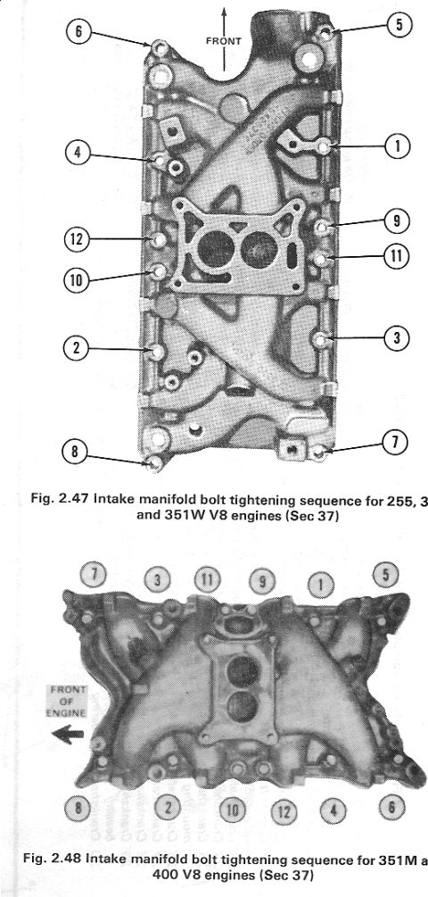



Instrument-panel wiring harness routing and connector location diagram with numbered component callouts and detail views.
Part of 1992-1996 Ford Bronco Exploded Parts Diagrams
This document is a factory-style exploded illustration (drawing number K17295-B) showing the wiring harness routing and electrical connector locations behind the dashboard/instrument panel of a Ford Bronco or F-Series truck. The main view depicts the instrument panel structure from the rear with the main dash harness routed across it, with 58 numbered callout balloons identifying individual connectors, relays, modules, grounds, retainers, and harness branches. Two enlarged inset views at the bottom provide detail: VIEW A shows a specific connector area (callouts 14, 2, and 46) on a wrapped harness section, and VIEW B shows a relay/module mounting area (callouts 43, 42, 16, 1, and 41) near the right side of the dash. Notably, the illustration contains only the numbered callouts and no accompanying legend or parts table, so the identity of each numbered component must be found on a companion legend page (the uploader's album contains related pages such as 'DashConnectors93a.jpg' that may hold the legend). The document is useful for locating a specific dash connector or relay physically once its callout number is known, and for understanding harness routing paths when diagnosing dash electrical problems or removing the instrument panel.
Is this accurate? Sign in to help verify it.
Frequently asked questions
- What does this diagram show?
- It is an exploded illustration of the dashboard/instrument panel wiring harness, showing the routing of the main dash harness and the locations of connectors, relays, and related components identified by numbered callouts 1 through 58.
- Does this diagram include a legend identifying each numbered part?
- No. Only the numbered callout balloons, the labels VIEW A and VIEW B, and the drawing number K17295-B appear; a legend would be on a companion page.
- What are the inset views at the bottom of the page?
- VIEW A is an enlarged detail showing callouts 14, 2, and 46 on a harness connector, and VIEW B is an enlarged detail showing callouts 43, 42, 16, 1, and 41 near a relay/module area of the dash.
- What is the drawing or figure number of this illustration?
- K17295-B, printed in the lower right corner.






No comments yet.