Home/
Registry/
Ford/
Bronco/
1992-1996/
“Eddie Bauer”/
Photo
supermotors.net/registry/media/1114628
Ford Bronco/F-Series Engine Block Ground Cable Diagram - Neg Battery Cable Views
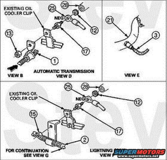
Exploded parts diagram with numbered callouts showing ground cable connections and oil cooler clip for automatic transmission and Lightning views.
This document is an exploded parts diagram showing the routing and attachment of the negative battery cable / engine block ground for a Ford truck. It is divided into multiple labeled views. View B and View D (marked "AUTOMATIC TRANSMISSION") show the negative cable terminal (labeled NEG) attaching near an existing oil cooler clip, with numbered callouts 1, 12, 13, 17, 25, and 28 identifying the cable eyelets, fasteners, and clip hardware. View E shows a cable segment with callouts 21 and 3. View F, marked "LIGHTNING ONLY," shows an alternate ground cable arrangement with a spring/loom-covered section (callouts 2 and 15) attaching at the existing oil cooler clip with the same NEG terminal hardware (callouts 12, 17, 25, 28); a note reads "FOR CONTINUATION SEE VIEW G." A reader can learn where the negative battery cable/ground strap eyelets bolt to the engine block, how the cable routes through the existing oil cooler clip, and that Lightning models use a different cable configuration. The diagram uses numeric callouts that reference a parts legend on another page (not included in this scan). The image bears SuperMotors.net watermarks.
Is this accurate? Sign in to help verify it.
Frequently asked questions
- Where does the negative battery cable ground to the engine block?
- Per Views B and D, the NEG cable eyelet (callout 17) attaches at the engine block near an existing oil cooler clip, secured with hardware shown as callouts 25 and 28.
- Is there a different ground cable setup for the Lightning?
- Yes. View F is marked "LIGHTNING ONLY" and shows a different cable arrangement (callouts 2 and 15) still routed through the existing oil cooler clip, with a note to see View G for continuation.
- Which view applies to automatic transmission trucks?
- View D is labeled "AUTOMATIC TRANSMISSION" and shows the ground cable attachment (callouts 1, 13, 12, 17, 25, 28) at the existing oil cooler clip.
- What do the numbered callouts (1, 2, 3, 12, 13, 15, 17, 21, 25, 28) refer to?
- They are parts callouts identifying cable eyelets, fasteners, and clips in each view; the legend defining each number is not included on this page of the scan.
Comments
More from this build







No comments yet.