Ford Bronco, E-150/F-150 & E/F-250-350 Parking Brake Assembly Diagram

Reference · 1992-1996 BroncoAll 169 exploded parts diagrams
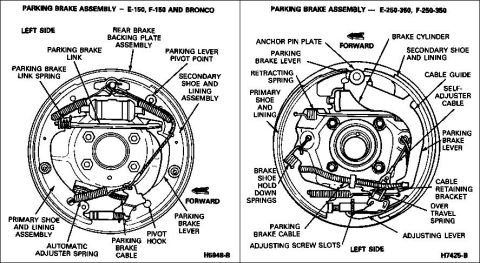




Labeled parking brake assembly diagrams for E-150/F-150/Bronco and E/F-250-350 showing shoes, springs and cables.
Part of 1992-1996 Ford Bronco Exploded Parts Diagrams
This document is a two-panel labeled illustration of Ford rear drum parking brake assemblies, shown from the left side of the vehicle. The left diagram covers the E-150, F-150 and Bronco and identifies the rear brake backing plate assembly, parking brake link and link spring, parking lever pivot point, secondary shoe and lining assembly, primary shoe and lining assembly, automatic adjuster spring, parking brake cable, pivot hook, and parking brake lever, with an arrow indicating the forward direction (figure reference H5948-B). The right diagram covers the E-250-350 and F-250-350 heavier-duty trucks and labels the anchor pin plate, brake cylinder, secondary and primary shoes and linings, retracting spring, cable guide, self-adjuster cable, parking brake levers, brake shoe hold down springs, cable retaining bracket, over travel spring, parking brake cable, adjusting screw slots, and adjusting lever (figure reference H7425-B). A reader can use this page to identify each component inside the rear drum, understand how the parking brake lever, link, and cable interact with the shoes, and compare the light-duty versus heavy-duty parking brake hardware layouts before disassembly, inspection, or reassembly of the rear drum brakes.
Is this accurate? Sign in to help verify it.
Frequently asked questions
- What parking brake components are shown for the Ford Bronco and F-150 rear drum?
- The E-150, F-150 and Bronco diagram labels the rear brake backing plate assembly, parking brake link and link spring, parking lever pivot point, secondary shoe and lining assembly, primary shoe and lining assembly, automatic adjuster spring, parking brake cable, pivot hook, and parking brake lever.
- How does the heavy-duty E-250-350 / F-250-350 parking brake assembly differ in labeled parts?
- The E-250-350/F-250-350 diagram additionally identifies an anchor pin plate, brake cylinder, retracting spring, cable guide, self-adjuster cable, brake shoe hold down springs, cable retaining bracket, over travel spring, adjusting screw slots, and adjusting lever.
- Which side of the vehicle do these diagrams show?
- Both diagrams are labeled 'LEFT SIDE' and include arrows indicating the FORWARD direction of the vehicle.
- Where does the parking brake cable attach in these assemblies?
- In both diagrams the parking brake cable enters at the lower area of the backing plate and connects to the parking brake lever; the heavy-duty version routes through a cable retaining bracket.






No comments yet.