Ford Vacuum Brake Booster Cutaway Diagram - Reaction Disc & Push Rod (Bronco)
Reference · 1992-1996 BroncoAll 169 exploded parts diagrams
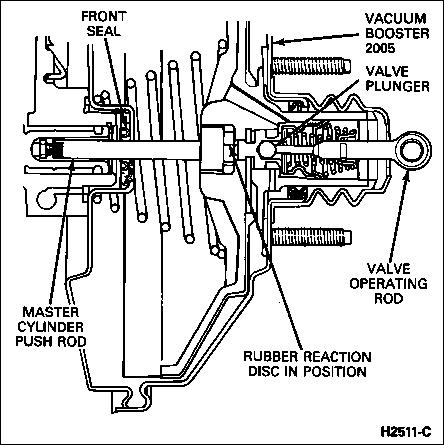






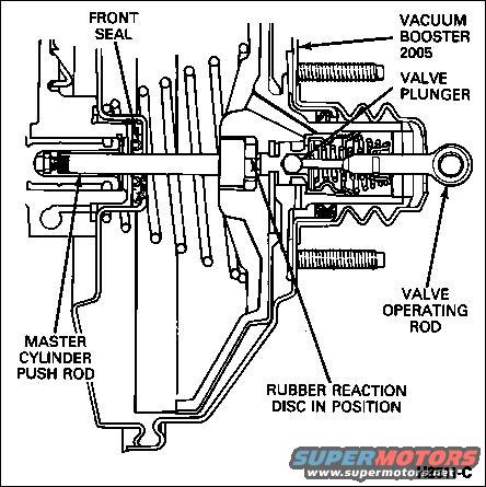
Cutaway of a Bendix 2005-type vacuum brake booster showing internal valve plunger, valve operating rod, rubber reaction disc in position, master cylinder push rod and front seal.
Part of 1992-1996 Ford Bronco Exploded Parts Diagrams
This document is a cutaway (cross-section) technical illustration of a vacuum brake booster assembly, showing the internal arrangement of its major components. Callout labels identify the front seal at the master cylinder side of the booster, the vacuum booster itself (labeled with base part reference 2005), the valve plunger inside the booster's control valve housing, the valve operating rod that extends rearward toward the brake pedal, the master cylinder push rod extending forward from the booster, and the rubber reaction disc shown in its installed position between the plunger and push rod. The diagram illustrates how the pedal input side (valve operating rod and plunger) connects through the rubber reaction disc to the output push rod that actuates the master cylinder, with the booster diaphragm return spring visible in section. The figure carries the Ford illustration reference number H2511-C. A reader can learn the relative positions of the booster's internal parts, which is useful when adjusting the master cylinder push rod, replacing the front seal, or verifying that the rubber reaction disc is correctly seated during booster service or overhaul. The document itself contains no year, model, or engine applicability statements; it was filed by the uploader with a 1992 Ford Bronco.
Is this accurate? Sign in to help verify it.
Frequently asked questions
- What internal components of the vacuum brake booster are shown in this cutaway?
- The diagram labels the front seal, the vacuum booster (2005), the valve plunger, the valve operating rod, the master cylinder push rod, and the rubber reaction disc in position.
- Where is the rubber reaction disc located in the booster?
- The callout shows the rubber reaction disc positioned inside the booster's central hub, between the valve plunger and the master cylinder push rod.
- What connects the brake pedal side to the master cylinder in this diagram?
- The valve operating rod enters the rear of the booster and acts on the valve plunger; force is transmitted through the rubber reaction disc to the master cylinder push rod at the front.
- What reference numbers appear on this diagram?
- The vacuum booster is labeled with the number 2005, and the illustration carries the figure reference H2511-C.






No comments yet.