SuperMotors SuperMotors SUPERMOTORS Search: try “orange Bronco on 35s”
Home/ Registry/ Ford/ Bronco/ 1992-1996/ “The Bronco”/ Photo supermotors.net/registry/media/254807

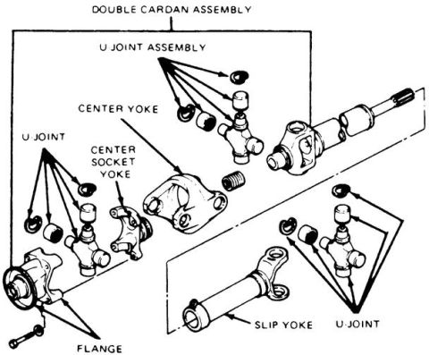
Ford Bronco Double Cardan Driveshaft Joint Exploded Diagram - U-Joints & Yokes

Double cardan driveshaft U-joint exploded assembly diagram with labels
Double cardan driveshaft U-joint exploded assembly diagram with labelsOriginal file
Double cardan driveshaft U-joint exploded assembly diagram with labels

Reference · 1992-1996 BroncoAll 169 exploded parts diagrams
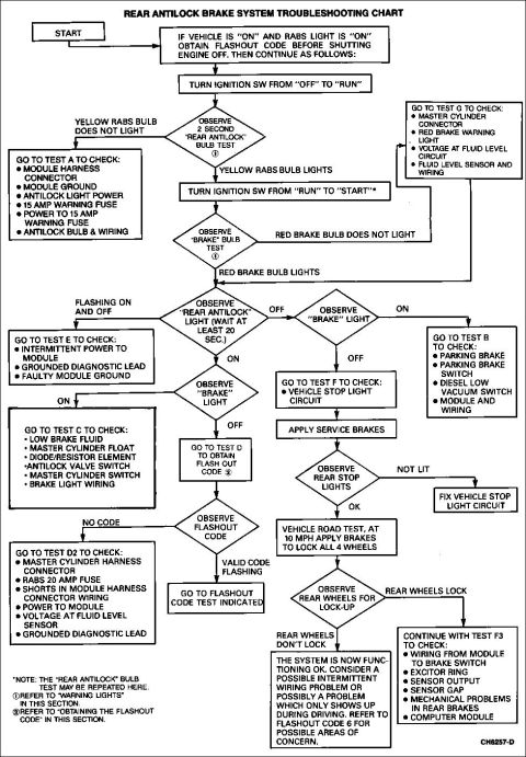
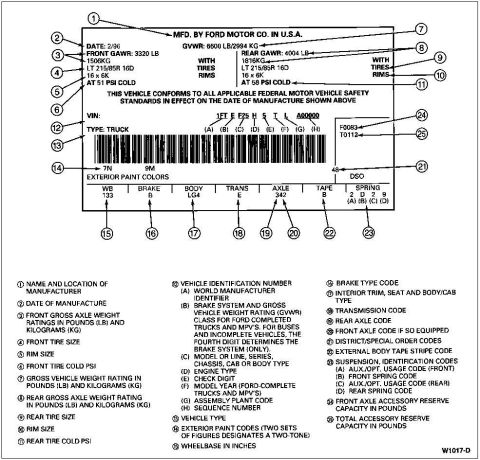
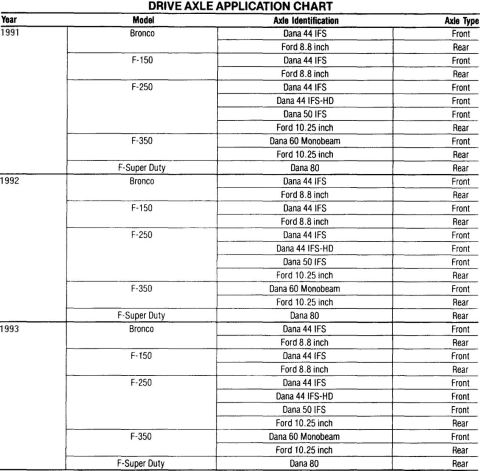
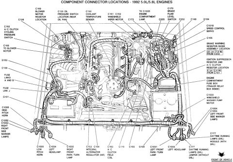
Ford Bronco Fuel Pump Sender & Reservoir Diagram - Wiring & Fuel Flow (A12768-E) Ford Bronco Exhaust System Exploded Diagram - Catalytic Converter & Muffler 1980-1995 Ford Bronco Cab/Body Mount Bushing Installation Instructions Ford Bronco Double Cardan Driveshaft Joint Exploded Diagram - U-Joints & Yokes 1992-96 Ford F-Series & Bronco Door Latch & Mechanisms Exploded Diagram 1978-79 Ford Bronco Power Tailgate Window Controls Exploded Parts Diagram Ford Bronco, E-150/F-150 & E/F-250-350 Parking Brake Assembly Diagram Ford Vacuum Brake Booster Cutaway Diagram - Reaction Disc & Push Rod (Bronco) 1996 Ford Bronco/F-150 Distributor Exploded Parts Diagram & Installation 03-07A-6 Ford Bronco Front Coil Spring & Shock Absorber Exploded Diagram (F2858-Q) Ford Bronco/F-Series Engine Block Ground Cable Diagram - Neg Battery Cable Views Instrument panel 04320 exploded view with finish panel 044D70, headlamp switch knob 11666 and mouldings 169exploded parts diagrams1992-1996 Ford Bronco More reference Trailer Connector Wiring Diagram - 4-Pin Flat, 6-Pin Round & 7-Blade PinoutsWiring diagram Ford RABS Rear Antilock Brake System Troubleshooting Chart (1992 Bronco)Service procedure Ford truck certification label with 25 numbered callouts explaining GVWR, tire, VIN and code fieldsSpec plate '91-93 Ford truck drive axle application chart for Bronco, F-150, F-250, F-350 and F-Super DutyManual page 1992 Ford Bronco/F-Series 5.0L 5.8L Engine Compartment Connector LocationsSchematic Ford 5.0L V8 Vacuum Hose Routing Diagram - EGR, AIR, FPRC & Carbon CanisterVacuum routing Ford 255/302/351W & 351M/400 V8 Intake Manifold Bolt Tightening SequenceTorque spec Brake Booster to Master Cylinder Adapter Plate Blueprint - Ford Bronco SwapBlueprint 1994-1995 BMW 3 Series Owner's Manual Booklet Set - Warranty, Radio & AccessoriesBrochure Ford Bronco/F-Series Fuse 18 (10A) - Speedometer, Air Bag, Shift ControlFuse chart

Exploded assembly diagram of a double cardan driveshaft labeling U-joints, center yoke, socket yoke, slip yoke and flange.

Part of 1992-1996 Ford Bronco Exploded Parts Diagrams

AI caption · Photo 111 of 272

This document is an exploded parts diagram of a double cardan (CV-style) driveshaft assembly. It shows the components of the double cardan joint in exploded view, with labeled callouts identifying each major part: the double cardan assembly as a whole, a U-joint assembly (shown with its cross, bearing caps, and snap rings), the center yoke, the center socket yoke, a second U-joint (also shown with its cross, caps, and retaining clips), the slip yoke with its splined shaft, and the flange that bolts to the drivetrain component. The illustration depicts how the two universal joints, center yoke, and center socket yoke stack together between the flange on one end and the slip yoke and shaft on the other. A reader can learn the assembly order and relative position of every component in the double cardan joint, which is useful when disassembling, inspecting, or rebuilding this type of driveshaft joint. The diagram contains no part numbers, torque specifications, year/model applicability, or written instructions, only component name labels with arrows pointing to the illustrated parts.

Is this accurate? Sign in to help verify it.

Frequently asked questions

What parts make up a double cardan driveshaft assembly?
According to the diagram, the double cardan assembly includes two U-joint assemblies, a center yoke, a center socket yoke, a slip yoke, and a flange.
What sits between the two U-joints in a double cardan joint?
The center yoke and the center socket yoke are shown positioned between the two U-joint assemblies.
What connects the double cardan joint to the driveshaft?
The diagram shows a slip yoke with a splined shaft on one end and a flange on the other end of the assembly.
Does this diagram include torque specs or part numbers?
No. It is an exploded illustration with component name labels only; no part numbers, torque values, or instructions are shown.


Comments

No comments yet.

More 1992-1996 Broncos