1992-96 Ford F-Series & Bronco Door Latch & Mechanisms Exploded Diagram

Reference · 1992-1996 BroncoAll 169 exploded parts diagrams
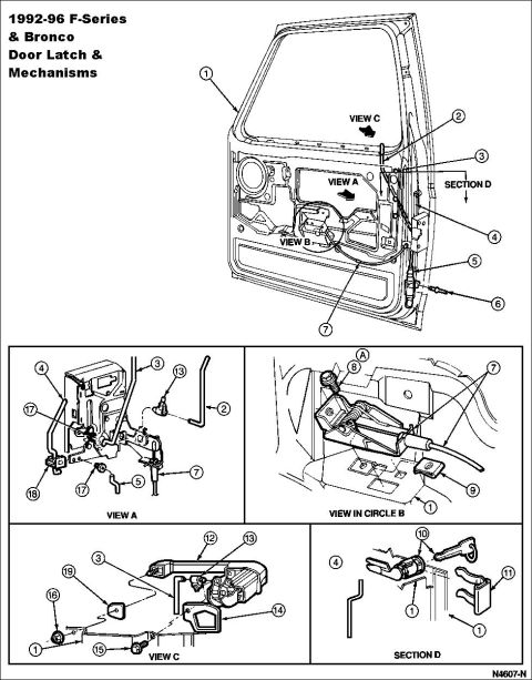




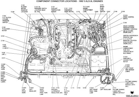
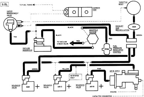
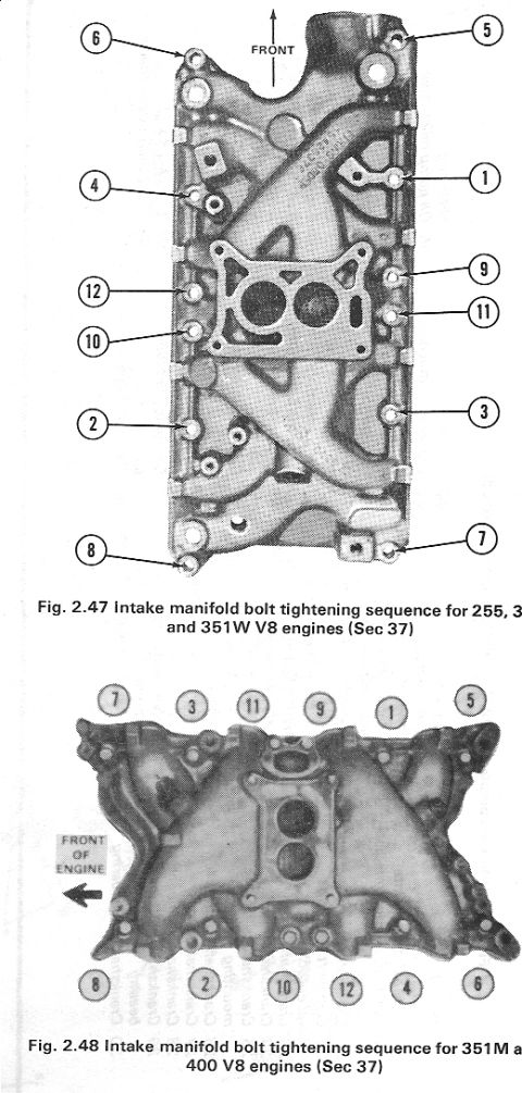



Exploded parts diagram of 1992-96 F-Series/Bronco door latch and mechanisms with numbered callouts and detail views.
Part of 1992-1996 Ford Bronco Exploded Parts Diagrams
This document is an exploded parts / assembly illustration from a Ford factory service reference covering the door latch and mechanisms for 1992-96 F-Series trucks and Bronco. The main drawing shows a front door shell with its inner panel exposed, indicating the locations of the latch, lock cylinder, rods, and handle components, with numbered callouts 1 through 7 and directional arrows referencing four detail views: VIEW A, VIEW B (circle B), VIEW C, and SECTION D. VIEW A details the door latch assembly area with callouts 2, 3, 4, 5, 7, 13, 17, and 18, showing the latch, actuating rods, and clips. VIEW IN CIRCLE B shows the inside door handle/remote control mechanism and cable (callouts 1, 7, 8, 9). VIEW C illustrates the outside door handle, its gasket/seal, retaining screw, and linkage (callouts 1, 3, 12, 13, 14, 15, 16, 19). SECTION D shows the door lock cylinder and its retaining clip installation (callouts 1, 4, 10, 11). The drawing carries the Ford illustration number N4607-N. A reader can use this diagram to identify the relative positions and assembly relationships of door latch hardware, though no textual legend with part names or part numbers is included on this page.
Is this accurate? Sign in to help verify it.
Frequently asked questions
- What vehicles does this door latch diagram cover?
- The document states it covers 1992-96 F-Series and Bronco door latch and mechanisms.
- What detail views are included in the diagram?
- It includes VIEW A, VIEW IN CIRCLE B, VIEW C, and SECTION D, each showing a different area of the door latch and handle mechanisms.
- Does the diagram show the door lock cylinder installation?
- Yes, SECTION D shows the lock cylinder area with callouts 10, 11, 4, and 1, including what appears to be the cylinder and its retaining clip.
- Is there a parts legend with names or part numbers on this page?
- No, the page shows only numbered callouts (1-19) and view labels; no legend, part names, or part numbers are printed except the illustration reference N4607-N.






No comments yet.