Home/
Registry/
Nissan/
Micra/
1983-1992/
1990 Nissan Micra/
Photo
supermotors.net/registry/media/294110
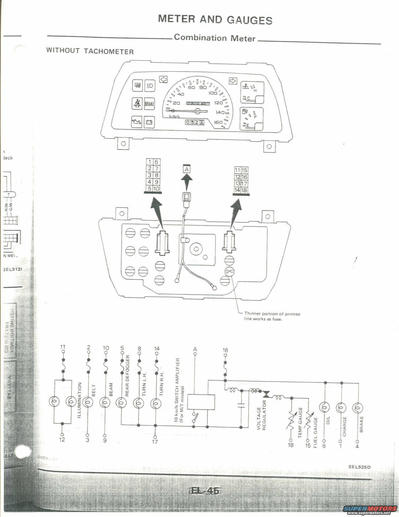
Nissan Micra Combination Meter Wiring Diagram (No Tach) - EL-45 Cluster Pinout
Reference · 1983-1992 MicraAll 23 wiring diagrams
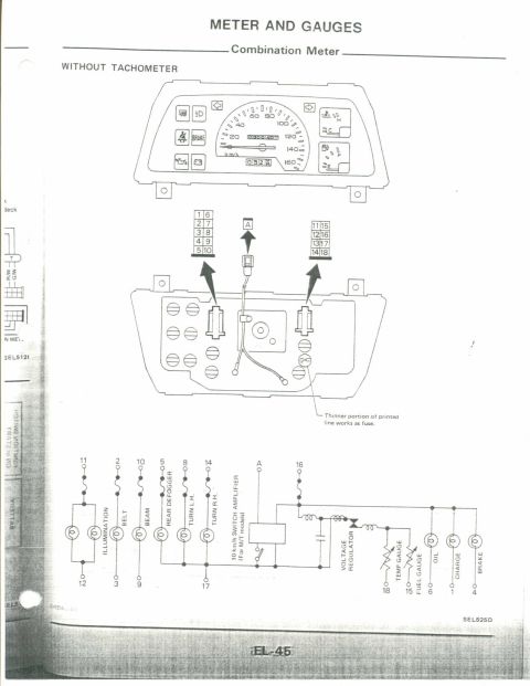
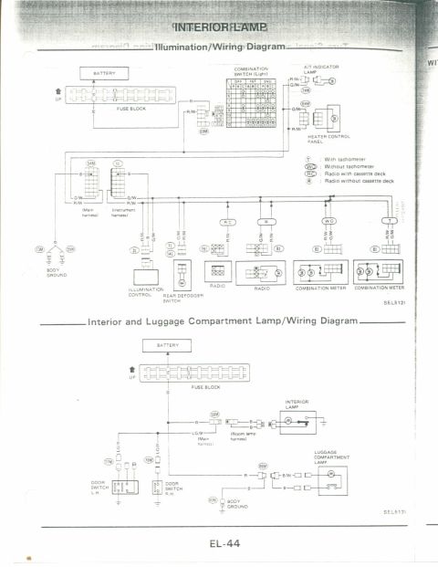
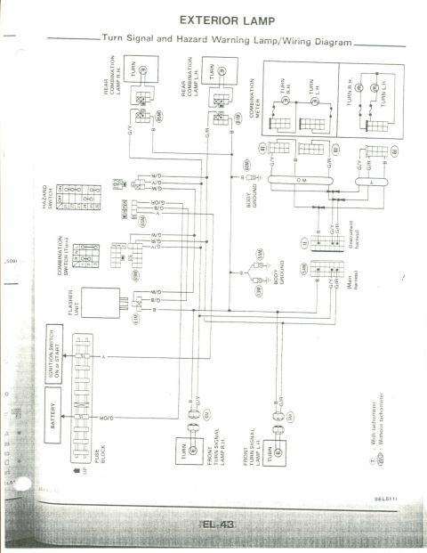
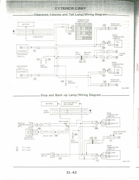
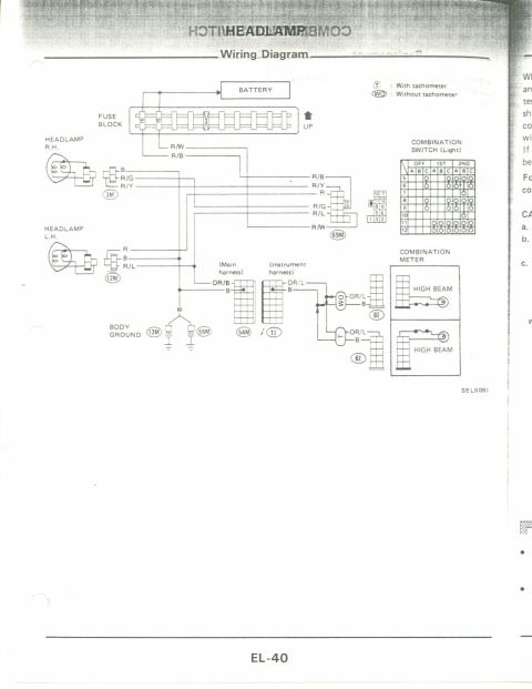

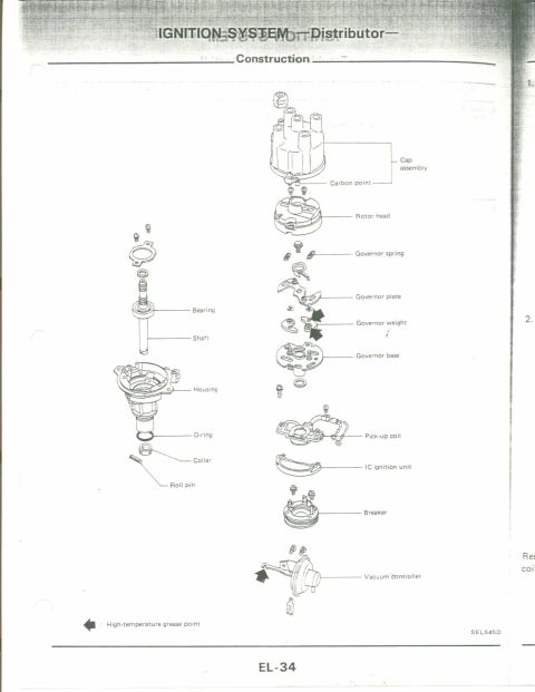
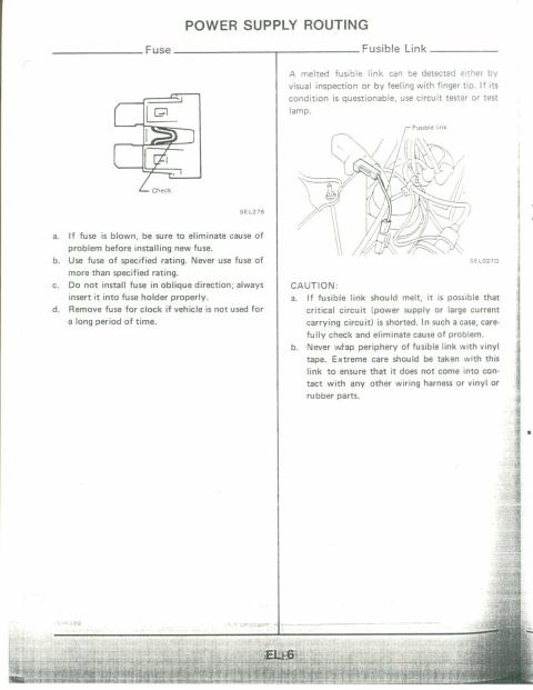
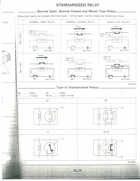
Combination meter (without tachometer) illustration plus a wiring diagram showing gauge connectors and circuit symbols.
Part of 1983-1992 Nissan Micra Wiring Diagrams
This is page EL-45 from a Nissan factory service manual, covering the "Meter and Gauges" section, specifically the combination meter for models WITHOUT a tachometer. The page shows three illustrations: (1) the front face of the instrument cluster with a 20-160 km/h speedometer, odometer/trip odometer, temperature gauge (C-H), fuel gauge (E-F), turn signal arrows, and warning lamps for rear defogger, headlamp high beam, seat belt, BRAKE, oil pressure, and charge; (2) the rear of the cluster showing the printed circuit board and three connectors with pin numbering, a 10-pin connector (pins 1-10), a single terminal "A," and an 8-pin connector (pins 11-18), with a note that the thinner portion of the printed line works as a fuse; and (3) a circuit schematic mapping each connector pin to its function: illumination (11/12), belt (2/3), beam (10/9), rear defogger (5), turn L.H. (8), turn R.H. (14), ground (17), 10 km/h switch amplifier terminal A (M/T models), voltage regulator feed (16), temp gauge (18), fuel gauge (15), oil (6), charge (1), and brake (4). Diagram reference codes SEL525D and SEL512I appear. Useful for diagnosing cluster wiring and gauge problems.
Is this accurate? Sign in to help verify it.
Frequently asked questions
- What connector pins control the instrument cluster illumination?
- Per the schematic, terminals 11 and 12 feed the illumination lamps of the combination meter.
- Which pins are used for the fuel and temperature gauges?
- Terminal 15 connects to the fuel gauge and terminal 18 to the temp gauge, both fed through the cluster's voltage regulator via terminal 16.
- How is the printed circuit on the back of the cluster protected?
- The document notes that the thinner portion of the printed line works as a fuse.
- What is terminal 'A' on the combination meter for?
- Terminal A connects to the 10 km/h switch amplifier, used on M/T (manual transmission) models.
- Which pins handle the turn signal indicators?
- Pin 8 is TURN L.H. and pin 14 is TURN R.H., with pin 17 serving as the shared ground side in the schematic.


No comments yet.