Home/
Registry/
Nissan/
Micra/
1983-1992/
1990 Nissan Micra/
Photo
supermotors.net/registry/media/294113
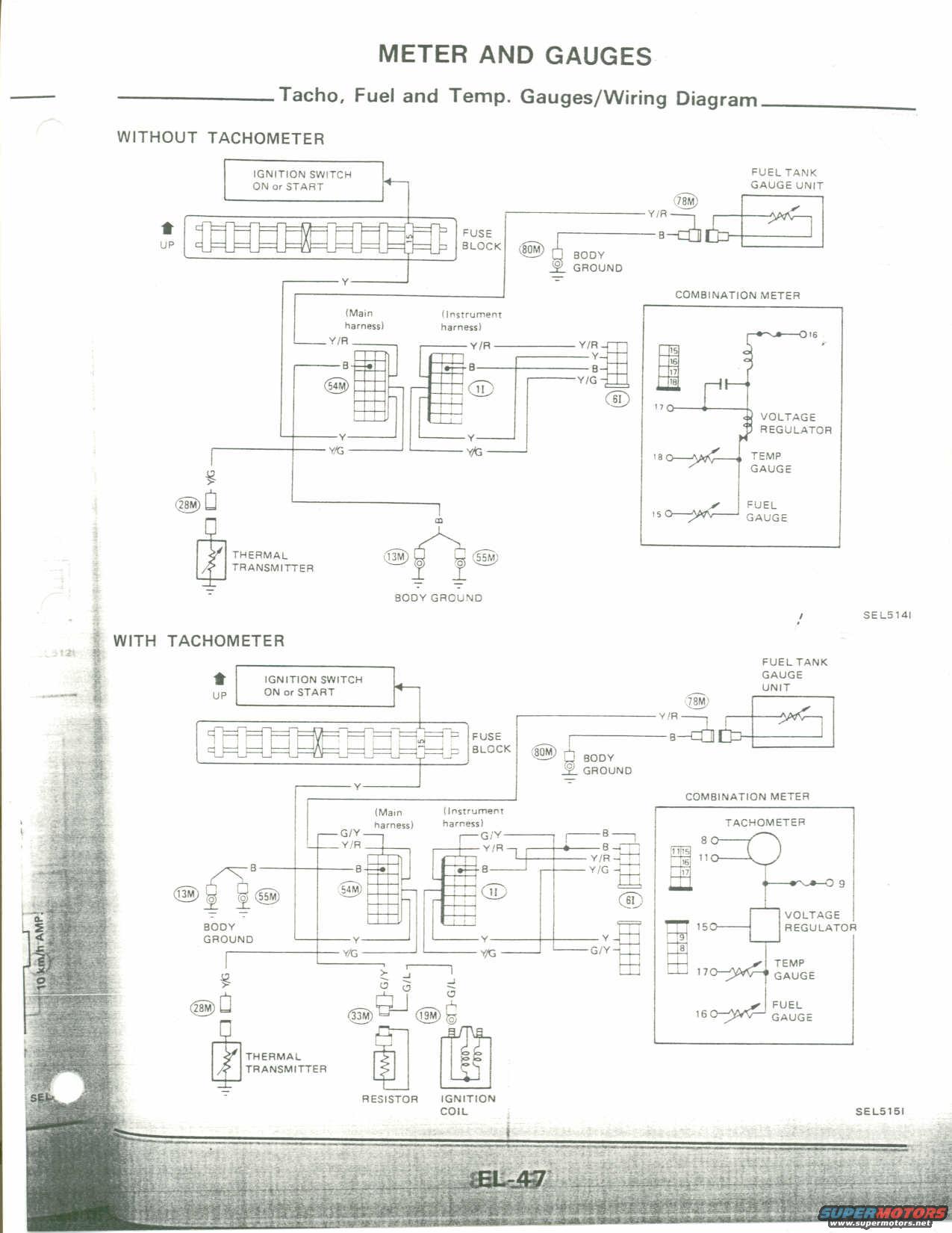
Nissan Micra Tachometer, Fuel & Temp Gauge Wiring Diagram - EL-47 Meter & Gauges
Reference · 1983-1992 MicraAll 23 wiring diagrams
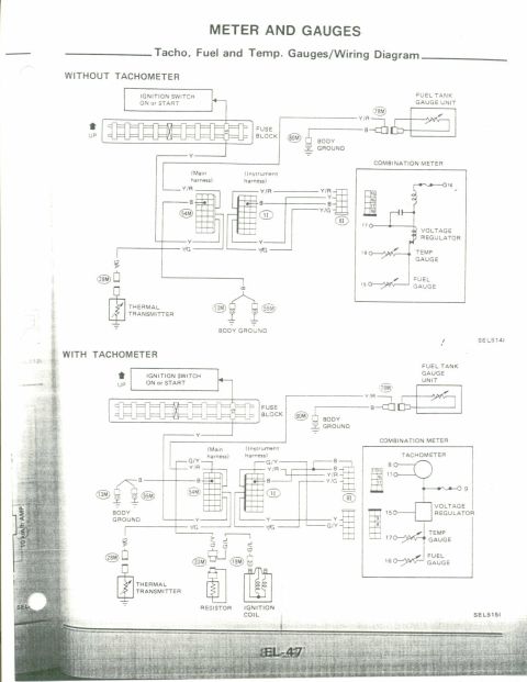
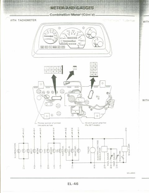
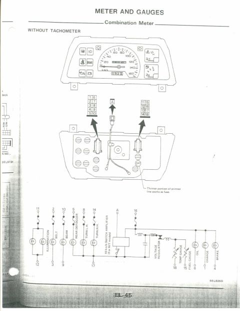

Factory instrument-cluster wiring diagram for tachometer, fuel and temperature gauges showing the combination meter, voltage regulator, thermal transmitter, fuel-tank gauge unit and ignition-coil tach feed.
Part of 1983-1992 Nissan Micra Wiring Diagrams
This is page EL-47 from a Nissan factory service manual, in the 'Meter and Gauges' section, showing the wiring diagrams for the tachometer, fuel gauge, and temperature (temp) gauge. Two schematic diagrams are shown: one for vehicles WITHOUT a tachometer (diagram reference SEL514I) and one for vehicles WITH a tachometer (diagram reference SEL515I). Both diagrams trace power from the ignition switch (ON or START) through the fuse block, then through the main harness and instrument harness to the combination meter, which contains the voltage regulator, temp gauge, fuel gauge, and (in the second diagram) the tachometer. Wire colors are labeled throughout: Y (yellow), Y/R, Y/G, B (black/ground), G/Y, and G/L. Connector references include 78M, 80M, 54M, 28M, 13M, 55M, 33M, 19M, 1I, and 6I, with combination meter pin numbers (15, 16, 17, 18 in the non-tach version; 8, 9, 11, 15, 16, 17 in the tach version). Sensor-side components include the fuel tank gauge unit, thermal transmitter (coolant temp sender), body grounds, and, on the tachometer version, a resistor and the ignition coil feeding the tach signal. A reader can use this page to trace and troubleshoot gauge and tachometer circuits.
Is this accurate? Sign in to help verify it.
Frequently asked questions
- What circuits are covered on this wiring diagram page?
- It covers the tachometer, fuel gauge, and temperature gauge wiring in the combination meter, with separate diagrams for vehicles with and without a tachometer (SEL514I and SEL515I).
- Where does the tachometer get its signal in the 'with tachometer' diagram?
- From the ignition coil, through a resistor, on G/L and G/Y wires via connectors 19M and 33M, into the instrument harness to the combination meter.
- What wire colors connect the fuel tank gauge unit?
- A Y/R wire (through connector 78M) to the gauge circuit and a B wire to body ground (connector 80M).
- What component sends the temperature signal to the temp gauge?
- The thermal transmitter, connected via a Y/G wire through connector 28M, with the temp gauge at pin 18 (without tach) or pin 17 (with tach) of the combination meter.
- Does the combination meter contain a voltage regulator?
- Yes, both diagrams show a voltage regulator inside the combination meter feeding the temp and fuel gauges.


No comments yet.