Home/
Registry/
Nissan/
Micra/
1983-1992/
1990 Nissan Micra/
Photo
supermotors.net/registry/media/294112
Nissan Micra Combination Meter Wiring Diagram (With Tachometer) - EL-46

Reference · 1983-1992 MicraAll 23 wiring diagrams
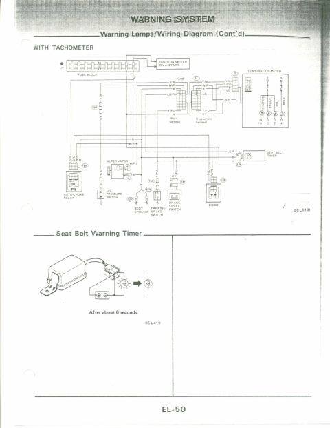
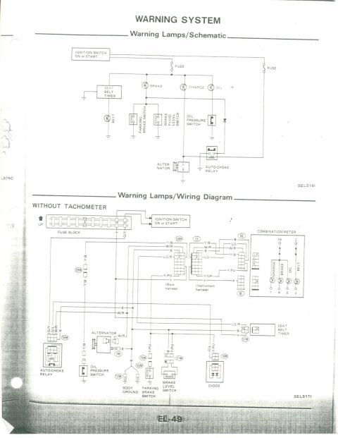
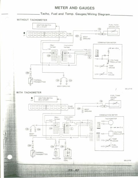
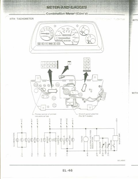
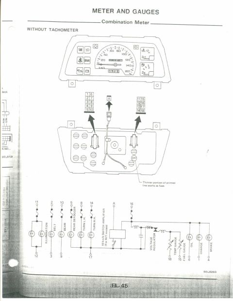
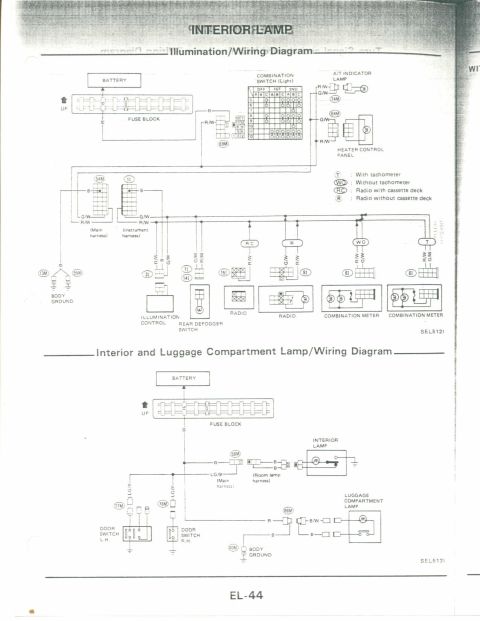
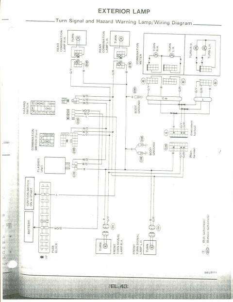
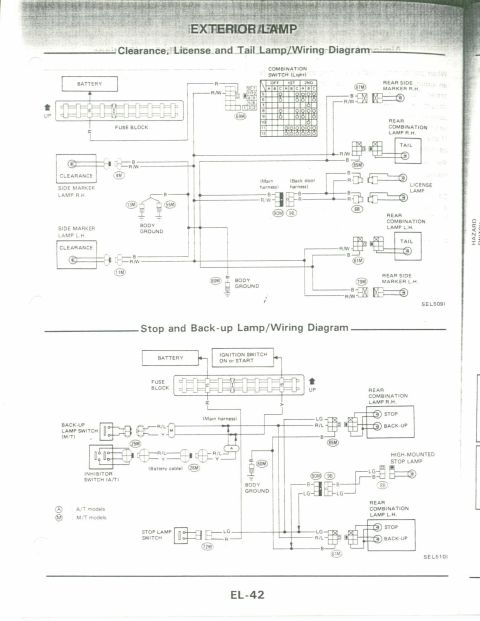

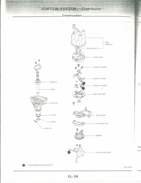
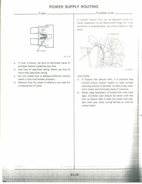
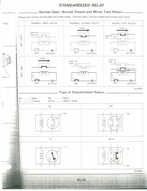
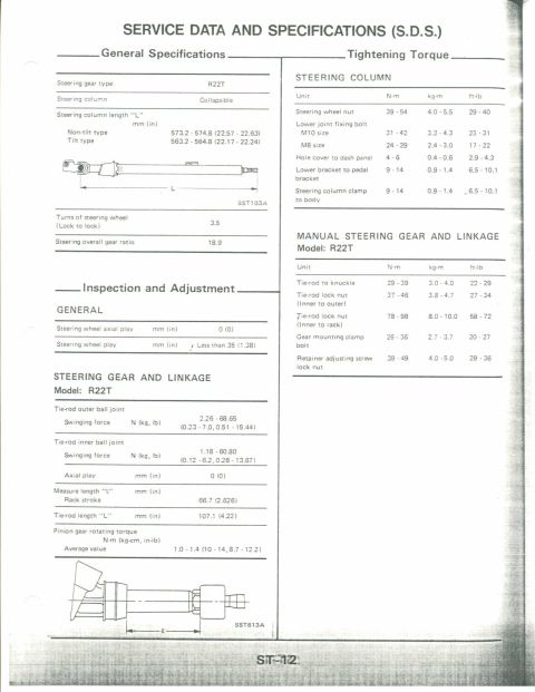
Combination meter (with tachometer) layout plus a wiring diagram showing gauge connectors, regulator and circuit symbols.
Part of 1983-1992 Nissan Micra Wiring Diagrams
This is page EL-46 from a Nissan factory service manual, in the 'Meter and Gauges' section, covering the 'Combination Meter (Cont'd)', specifically the version WITH TACHOMETER. The page includes three illustrations: (1) the instrument cluster face showing the tachometer (0-8 x1000 r/min), speedometer (20-160 km/h with MPH inner scale), odometer, temperature and fuel gauges, and warning lamp symbols; (2) a rear view of the meter housing identifying three electrical connectors, a 10-pin connector (terminals 1-10), a single-terminal connector 'A', and an 8-pin connector (terminals 11-18), with callouts noting that a 'thinner portion of printed line works as fuse' on the printed circuit and identifying the '10 km/h switch amplifier (For M/T models)'; and (3) an internal circuit diagram mapping each terminal to its function: illumination, belt, beam, charge, brake, oil, turn R.H./L.H., rear defogger indicators, the tachometer, electric voltage regulator, fuel gauge, temperature gauge, 10 km/h switch, and 10 km/h amplifier. The diagram reference is SEL405G. A reader can use this page to identify combination-meter connector terminal assignments and to understand the printed-circuit fuse feature when diagnosing gauge or warning-lamp faults.
Is this accurate? Sign in to help verify it.
Frequently asked questions
- What terminal numbers are used on the combination meter connectors?
- There are three connectors: a 10-pin connector with terminals 1-10, a single terminal marked A, and an 8-pin connector with terminals 11-18 arranged as 11/15, 12/16, 13/17, 14/18.
- How is the combination meter's printed circuit protected?
- The document notes that a 'thinner portion of printed line works as fuse', a narrowed section of the printed circuit trace acts as a fuse.
- What is the 10 km/h switch amplifier and which models have it?
- The 10 km/h switch amplifier is mounted on the rear of the combination meter and is used on M/T (manual transmission) models. It connects via terminal A and works with the 10 km/h switch (terminal 17).
- Which terminals serve the turn signal indicators?
- In the circuit diagram, Turn R.H. is on terminal 18 and Turn L.H. is on terminal 14, both grounding through terminal 11 with Rear Def.
- What gauges and warning lamps are in this cluster version?
- The 'with tachometer' cluster contains a tachometer, speedometer, fuel and temperature gauges (fed through an electric voltage regulator), plus illumination, belt, beam, charge, brake, oil, turn right/left, and rear defogger indicator lamps.


No comments yet.