1994 Ford F-Series/Bronco Ignition Wire Routing Diagram - Firing Order 13726548

Reference · 1992-1996 BroncoAll 101 manual pages
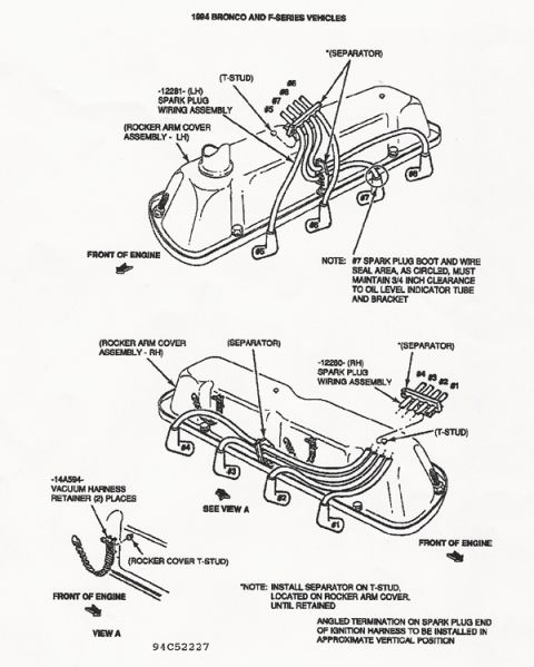
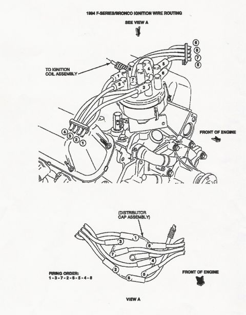
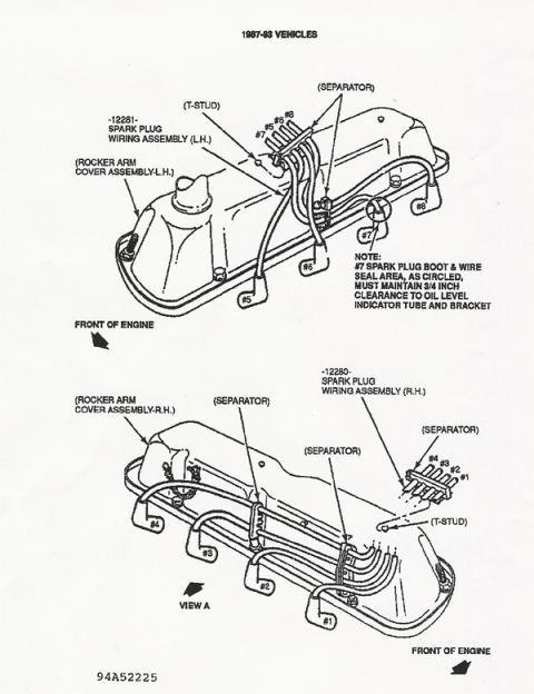
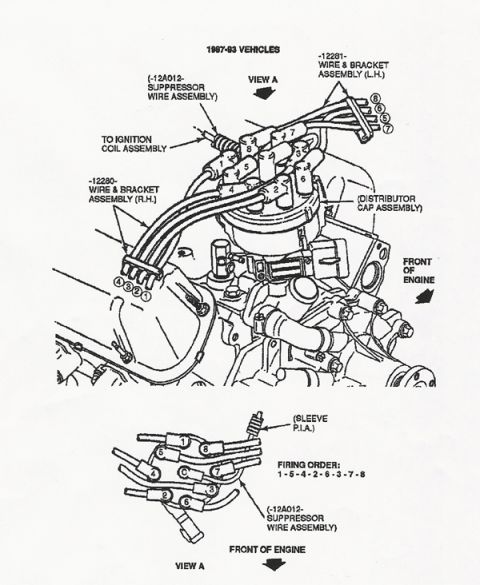

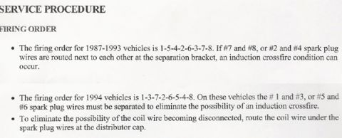








Manual figure of 1994 F-Series/Bronco ignition wire routing to the distributor cap with firing order 1-3-7-2-6-5-4-8.
Part of 1992-1996 Ford Bronco Manual Pages
This document is a scanned manual page titled "1994 F-Series/Bronco Ignition Wire Routing." It contains two line-art illustrations. The upper illustration shows a top view of the engine with the distributor cap assembly, the ignition coil connection (labeled "TO IGNITION COIL ASSEMBLY"), and the routing of the eight spark plug wires through two wire separator brackets, the left bracket carrying wires 4, 3, 2, 1 and the right bracket carrying wires 6, 8, 7, 5. An arrow indicates the front of the engine for orientation. The lower illustration, labeled "VIEW A," shows the distributor cap assembly from above with each of the eight cap towers numbered (1, 3, 7, 2, 6, 5, 4, 8) so the reader can identify which spark plug wire connects to which distributor tower. The firing order is explicitly stated as 1-3-7-2-6-5-4-8. A reader can use this page to correctly route and connect spark plug wires from the distributor cap to the cylinders on a 1994 Ford F-Series truck or Bronco V8 engine, avoiding crossed wires and misfires after a tune-up or distributor cap replacement.
Is this accurate? Sign in to help verify it.
Frequently asked questions
- What is the firing order shown in this diagram?
- The firing order is 1-3-7-2-6-5-4-8, as stated below the distributor cap illustration (View A).
- What vehicles does this ignition wire routing diagram cover?
- The document is titled "1994 F-Series/Bronco Ignition Wire Routing," so it covers 1994 Ford F-Series trucks and the Bronco.
- How are the spark plug wires arranged in the wire separators?
- In the upper illustration, the left-side wire separator holds wires 4, 3, 2, 1 and the right-side wire separator holds wires 6, 8, 7, 5.
- How are the distributor cap towers numbered?
- View A shows the distributor cap assembly with towers labeled 1, 3, 7, 2, 6, 5, 4, and 8 around the cap, matching the firing order sequence.
- Does the diagram show engine orientation?
- Yes, both illustrations include a "FRONT OF ENGINE" arrow to indicate orientation for correct wire routing.






No comments yet.