Home/
Registry/
Ford/
Bronco/
1992-1996/
1996 Ford Bronco/
Photo
supermotors.net/registry/media/1110168
1996 Ford Bronco/F-150 4-Wheel ABS Quick Test Chart - Pin & Resistance Specs

Reference · 1992-1996 BroncoAll 98 manual pages
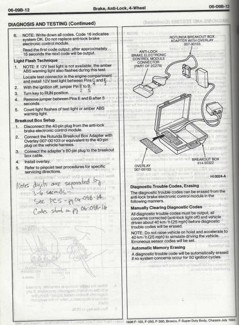
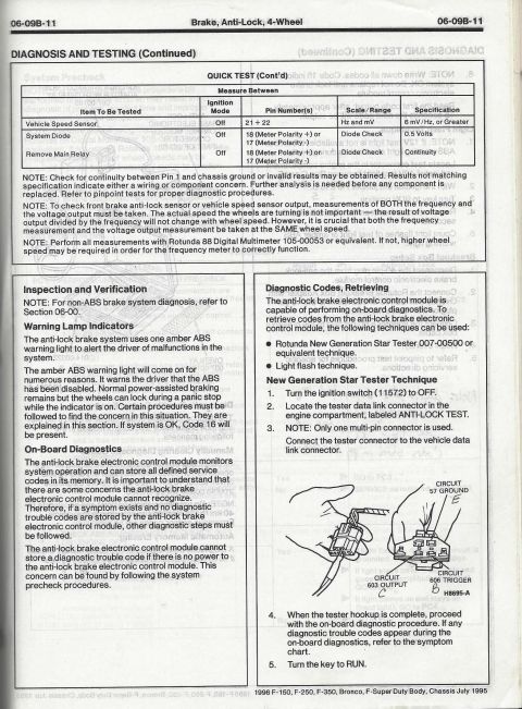
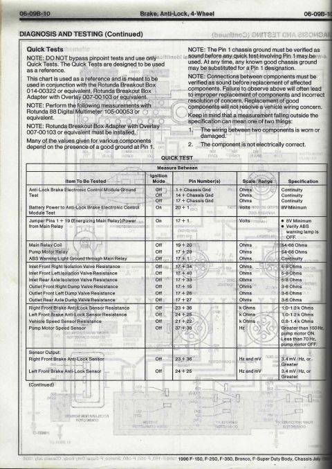
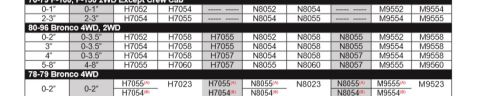








Scanned Ford service manual page with an ABS quick-test table listing items, ignition mode, pin numbers, scale/range, and specifications.
Part of 1992-1996 Ford Bronco Manual Pages
This is page 06-09B-10 from the 1996 Ford Body/Chassis service manual (covering F-150, F-250, F-350, Bronco, and F-Super Duty), from the section 'Brake, Anti-Lock, 4-Wheel, Diagnosis and Testing.' It presents the ABS 'Quick Tests' reference chart, intended for use with the Rotunda Breakout Box 014-00322, the Breakout Box Adapter with Overlay 007-00103, and the Rotunda 88 Digital Multimeter 105-00053 (or equivalents). Cautions state that Quick Tests are only a reference (pinpoint tests must not be bypassed), that the Pin 1 chassis ground must be verified before testing, and that connections must be verified before replacing components. The Quick Test table lists each item to be tested (ABS control module ground, battery power to module, main relay coil, pump motor relay, isolation and dump valve resistances, front wheel anti-lock sensors, vehicle speed sensor, pump motor speed sensor, and sensor outputs), along with ignition mode, breakout box pin pairs to measure between, meter scale/range, and specifications (e.g., isolation valves 5-8 ohms, dump valves 3-6 ohms, front sensors 1.0-1.2 k ohms, main relay coil 54-68 ohms, sensor output 3.4 mV/Hz or greater). The table continues on the next page.
Is this accurate? Sign in to help verify it.
Frequently asked questions
- What resistance should the ABS isolation valves read on a 1996 Ford Bronco/F-Series?
- Per the Quick Test chart, the inlet front right (pins 17+34), inlet front left (17+40), and inlet rear axle (17+33) isolation valves should each read 5-8 Ohms with the ignition Off.
- What is the specification for the front wheel ABS sensor resistance?
- Right front (pins 23+36) and left front (pins 24+25) brake anti-lock sensors should each measure 1.0-1.2 k Ohms with the ignition Off; the vehicle speed sensor (pins 21+22) should read 0.8-1.4 k Ohms.
- What tools are required to perform these ABS Quick Tests?
- Rotunda Breakout Box 014-00322 or equivalent, Rotunda Breakout Box Adapter with Overlay 007-00103 or equivalent, and Rotunda 88 Digital Multimeter 105-00053 or equivalent.
- What should the main relay coil and pump motor relay resistance be?
- The main relay coil (pins 19+20) and pump motor relay (pins 17+29) should each read 54-68 Ohms with the ignition Off.
- What does the pump motor speed sensor frequency indicate?
- Measured at pins 37+38: greater than 150 Hz means the pump motor is ON; less than 70 Hz means the pump motor is OFF.






No comments yet.