Home/
Registry/
Ford/
Bronco/
1992-1996/
1996 Ford Bronco/
Photo
supermotors.net/registry/media/1050300
1994 Ford Bronco/F-150 Transfer Case 4x4 Electronic Shift & 4L Power Flow 07-07-7

Reference · 1992-1996 BroncoAll 98 manual pages
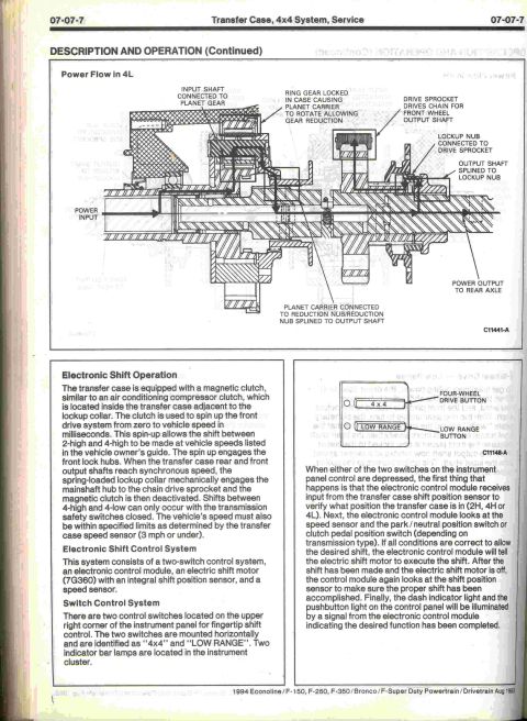








Transfer case description-and-operation manual page with a 4-Low power-flow cutaway and electronic shift operation text.
Part of 1992-1996 Ford Bronco Manual Pages
This is page 07-07-7 from the 1994 Ford Econoline / F-150, F-250, F-350 / Bronco / F-Super Duty Powertrain/Drivetrain service manual (dated Aug 1993), covering the Transfer Case, 4x4 System, Service section. The top half shows a labeled cutaway diagram (C11441-A) illustrating power flow through the transfer case in 4L (four-wheel-drive low), with callouts for the input shaft/planet gear, ring gear locked in case for gear reduction, planet carrier and reduction nub, drive sprocket and chain for the front wheel output shaft, lockup nub, and output shaft, showing power output to the rear axle. The lower half describes Electronic Shift Operation: the transfer case uses a magnetic clutch (similar to an A/C compressor clutch) to spin up the front drive system, allowing shifts between 2-high and 4-high at speed; 4-high to 4-low shifts require the transmission safety switches closed and vehicle speed of 3 mph or under. The Electronic Shift Control System consists of two switches, an electronic control module, an electric shift motor (7G360) with integral shift position sensor, and a speed sensor. It also describes the "4x4" and "LOW RANGE" instrument-panel pushbuttons (diagram C11148-A) and the ECM logic sequence for verifying and executing shifts.
Is this accurate? Sign in to help verify it.
Frequently asked questions
- How does the electronic shift transfer case shift between 2-high and 4-high?
- The transfer case uses a magnetic clutch, similar to an air conditioning compressor clutch, located inside the case adjacent to the lockup collar. It spins up the front drive system from zero to vehicle speed in milliseconds, engaging the front lock hubs. When the rear and front output shafts reach synchronous speed, the spring-loaded lockup collar mechanically engages the mainshaft hub to the chain drive sprocket and the magnetic clutch deactivates.
- What conditions are required to shift between 4-high and 4-low?
- Shifts between 4-high and 4-low can only occur with the transmission safety switches closed, and vehicle speed must be within specified limits as determined by the transfer case speed sensor, 3 mph or under.
- What components make up the electronic shift control system?
- A two-switch control system, an electronic control module, an electric shift motor (7G360) with an integral shift position sensor, and a speed sensor.
- Where are the 4x4 control switches located?
- Two control switches are on the upper right corner of the instrument panel, mounted horizontally and identified as "4x4" and "LOW RANGE". Two indicator bar lamps are located in the instrument cluster.
- How does power flow through the transfer case in 4L?
- The input shaft is connected to the planet gear; the ring gear is locked in the case causing the planet carrier to rotate, allowing gear reduction. The planet carrier connects to the reduction nub, which is splined to the output shaft. The drive sprocket drives the chain for the front wheel output shaft, and power outputs to the rear axle.






No comments yet.