SuperMotors SuperMotors SUPERMOTORS Search: try “orange Bronco on 35s”
Home/ Registry/ Ford/ Bronco/ 1978-1979/ “Lula Mae”/ Photo supermotors.net/registry/media/307027

Ford Bronco A/C Evaporator Assembly 18C424 Exploded Parts Diagram

Exploded diagram of A/C evaporator housing, air inlet duct, vacuum motor and de-icing switch
Exploded diagram of A/C evaporator housing, air inlet duct, vacuum motor and de-icing switchOriginal file
Exploded diagram of A/C evaporator housing, air inlet duct, vacuum motor and de-icing switch

Reference · 1978-1979 BroncoAll 79 exploded parts diagrams

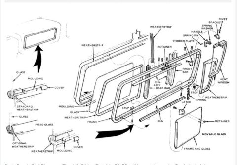
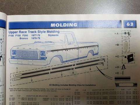
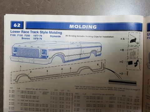
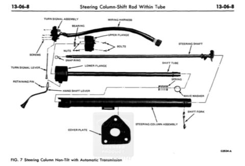
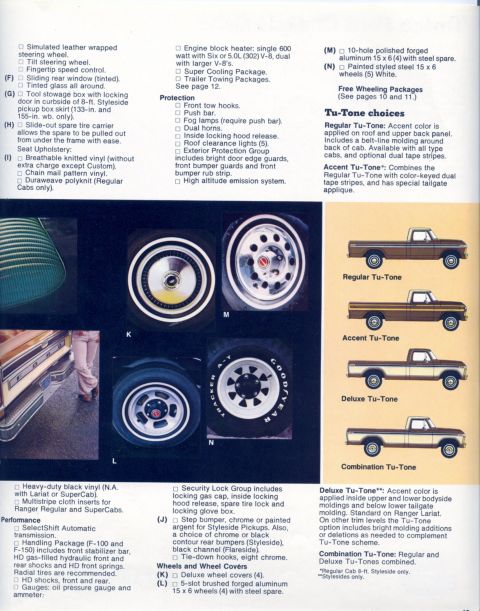
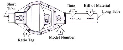
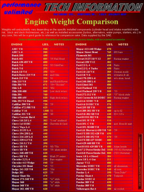
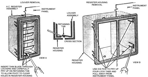
1978 Ford Bronco Hood Assembly Exploded Diagram - Hinge, Striker & Part Numbers 1978 Ford Bronco Radiator Grille & Support Exploded Parts Diagram 1978 Ford Bronco Front Fender & Apron Exploded Parts Diagram - Torque Specs Ford Bronco A/C Evaporator Assembly 18C424 Exploded Parts Diagram 1978 Ford Bronco Engine Oil Pump Exploded Diagram - Part Numbers & Assembly 1978 Ford Bronco Engine Mount Exploded Diagram - Insulators, Brackets & Torque Ford Bronco Door Window Regulator & Glass Exploded Parts Diagram Ford Truck & Bronco Door Latch, Lock & Handle Exploded Parts Diagram 1978-79 Ford Bronco/Truck Rear Slider & Fixed Glass Exploded Parts Diagram 1977-79 Ford F100/F150/F250 & 1978-79 Bronco Upper Race Track Molding Parts 1977-79 Ford F100 F150 F250 & 1978-79 Bronco Lower Race Track Molding Catalog Ford Non-Tilt Steering Column Exploded Diagram - Automatic, Shift Rod In Tube 79exploded parts diagrams1978-1979 Ford Bronco More reference 1979 Ford Pickup Brochure Page 19 - F-100/F-150 Options, Wheels & Tu-Tone PaintBrochure Dana 60 Axle ID Diagram - Bill of Material, Date Code, Model Number & Ratio TagSpec plate Engine weight comparison chart listing engines by make with weight in pounds and notesManual page Ford Bronco A/C Register & Louver Removal Diagram - Dash Vent ProcedureService procedure Piston Engine Cycle Animation Diagram - Single Cylinder Cross-SectionSchematic Ford 400 CID (6.6L) Vacuum Diagram - Calibration 9-62M-R10, 10-5-78Vacuum routing Bolt identification guide chart of head markings, grades, materials and tensile strengthsTorque spec Ford Bronco Wiring Diagram - Ignition, Wiper Motor & Back-Up Light CircuitsWiring diagram 1978 Ford Bronco Custom Bumper Build - SolidWorks CAD Assembly ScreenshotBlueprint 1979 Ford Bronco & F100-F350 Fuse Block Diagram - Fuse Positions & Amp RatingsFuse chart

Exploded parts diagram of an A/C evaporator and air inlet duct assembly with vacuum motor, hoses, de-icing switch and mounting screws.

Part of 1978-1979 Ford Bronco Exploded Parts Diagrams

AI caption · Photo 318 of 526

This document is an exploded parts diagram showing the A/C evaporator assembly and its mounting to the dash panel, uploaded as part of a Ford Bronco reference album. The illustration identifies the A/C evaporator assembly (part 18C424), the evaporator rear housing assembly (19A583), the air inlet duct (18C624), and the duct assembly (18A442). It also shows the outside-recirc door vacuum motor with its white vacuum hose, a vacuum line with a green and white stripe, and the de-icing switch mounted on the evaporator case. Fasteners are called out throughout: screws (including screw 55915-S2, 3 required, noted in two locations at the air inlet duct and duct assembly), nuts securing the housing studs through the dash panel, and caps covering fastener locations. A reader can learn the relative positions of the evaporator housing components on the engine-compartment side of the dash panel, which Ford basic part numbers correspond to each component, and where and how many fasteners are used to attach the air inlet duct and duct assembly. The diagram contains no year, model, or engine applicability text of its own.

Is this accurate? Sign in to help verify it.

Frequently asked questions

What is the Ford part number for the A/C evaporator assembly?
The diagram labels the A/C evaporator assembly as part 18C424.
What part number is the evaporator rear housing assembly?
The evaporator rear housing assembly is labeled 19A583.
How many screws are required to mount the duct assembly and air inlet duct?
The diagram calls out screw 55915-S2 with '3 REQ'D' in two locations, three required at each callout.
Which vacuum hose connects to the outside-recirc door vacuum motor?
A white vacuum hose is shown routing to the outside-recirc door vacuum motor; a hose with a green and white stripe is also identified.
Where is the de-icing switch located?
The de-icing switch is shown mounted on the A/C evaporator assembly case.

Comments

No comments yet.

More 1978-1979 Broncos