Home/
Registry/
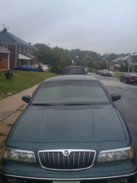
Mercury/
Grand Marquis/
1992-1997/
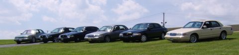
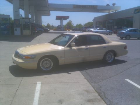
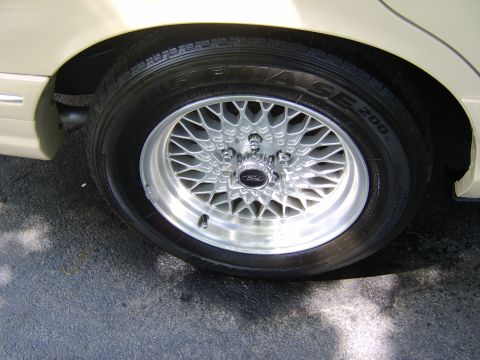
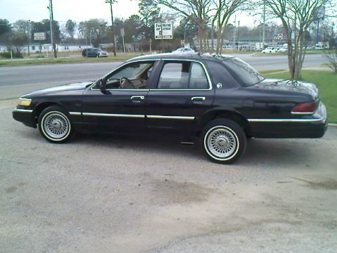
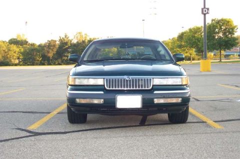
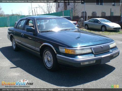
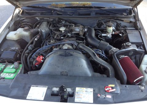
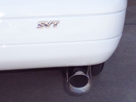
“The "LSE S/C"”/
Photo
supermotors.net/registry/media/310904
98-02 Ford CJB Hot in Run Wiring Diagram - Airbag, Cluster, ABS Circuits

Ford wiring diagram showing crankshaft sensor, instrument cluster and control circuits with connector and wire-color codes.
This document is a single-page automotive wiring diagram showing the 'Hot in Run' power distribution from the Central Junction Box (referenced to page 13-7 of the source manual). Two 10-amp fuses (positions 13 and 15) feed the circuits shown. Fuse 13 supplies circuit 964 (dark blue/light green, DB/LG) to splice S269, which branches to three pins (2, 10, and 12) of connector C277 at the Air Bag Electronic Crash Sensor (ECS), referenced to page 46-1. Fuse 15 supplies circuit 88 (black/white, BK/WH) to splice S231, which branches to: the Instrument Cluster via connector C255 and via C256 (digital cluster) or C251 (analog cluster), referenced to pages 60-6, 63-1 and 63-4; the Traction Control Switch via connector C297 (page 42-2); and through connectors C119M/C119F and C115M/C115F (including an Evac and Fill Connector, page 42-1) to pin 23 of the Anti-Lock Brake Module (pages 42-1, 42-2). A legend notes that one asterisk denotes 'with digital cluster' and two asterisks denote 'with analog cluster.' The diagram documents wire colors, circuit numbers, connector identifiers, and splice points for these run-powered systems.
Is this accurate? Sign in to help verify it.
Frequently asked questions
- What fuse and circuit power the Air Bag Electronic Crash Sensor (ECS)?
- A 10A fuse (position 13) in the Central Junction Box feeds circuit 964, a dark blue/light green (DB/LG) wire, through splice S269 to pins 2, 10, and 12 of connector C277 at the Air Bag Electronic Crash Sensor (page 46-1).
- What wire color is circuit 88 in this diagram?
- Circuit 88 is black/white (BK/WH). It is fed by a 10A fuse (position 15) in the Central Junction Box and distributed through splice S231.
- Which connector feeds the Anti-Lock Brake Module in this diagram?
- Circuit 88 BK/WH passes through connectors C119M/C119F and C115M/C115F (including the Evac and Fill Connector, page 42-1) to pin 23 of the Anti-Lock Brake Module (pages 42-1, 42-2).
- What do the asterisks in the diagram mean?
- One asterisk (*) means 'with digital cluster' and two asterisks (**) mean 'with analog cluster.' For example, connector C256 applies to the digital cluster and C251 to the analog cluster.
- Which connector goes to the Traction Control Switch?
- Connector C297, pin 1, receives circuit 88 BK/WH from splice S231; the Traction Control Switch is referenced on page 42-2.
Comments
More from this build

No comments yet.