Home/
Registry/
Mercury/
Grand Marquis/
1992-1997/
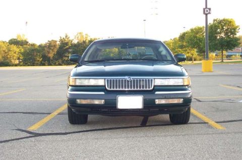
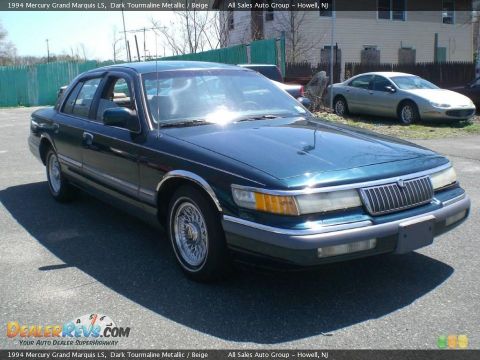
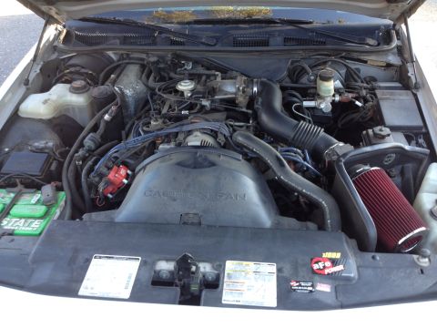
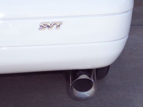
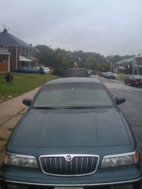
“The "LSE S/C"”/
Photo
supermotors.net/registry/media/310930
2002 Crown Victoria/Grand Marquis CJB Power Distribution Wiring Diagram 13-13

Crown Victoria/Grand Marquis '02 power-distribution wiring diagram showing fuses, splices and connector wire codes.
This is page 13-13 of the Power Distribution section from the 2002 Ford Crown Victoria / Mercury Grand Marquis wiring diagram manual. It shows two fused ignition-switched circuits from the P91 Central Junction Box (CJB, part 14A068). Fuse F2.4 (10A, hot in start or run) feeds circuit 964 on a 20-gauge DB/LG (dark blue/light green) wire through connector C212 (pin 18) and splice S229 to the B287 Occupant Classification Sensor (OCS) via connectors C312 (pin 12) and C3159a (pin 4), and to the A208 Restraints Control Module (14B321) via connector C310b (pins 1 and 7). Fuse F2.14 (10A, hot in run) feeds circuit 88 on a 20-gauge BK/WH (black/white) wire from feed circuit 489 (16 PK/BK, referenced to page 13-7) through splice S231 to the A30 Instrument Cluster via connectors C220b (pin 10), C220c (pins 2 and 7), and C2220a (pin 10, conventional cluster), and to the A7 ABS Control Module (2C219) via connectors C140 (pin 7) and C135 (pin 8). Cross-references to pages 13-7, 13-10, 13-15, and component sections 46-2, 60-7, 61-2, 61-5, and 42-1 are included.
This document covers 2002, which may differ from this 1996 Mercury Grand Marquis.
Is this accurate? Sign in to help verify it.
Frequently asked questions
- What fuse powers the Restraints Control Module and Occupant Classification Sensor on the 2002 Crown Victoria/Grand Marquis?
- Fuse F2.4, a 10A fuse in the P91 Central Junction Box (CJB, 14A068), hot in start or run. It feeds circuit 964 (20 gauge DB/LG wire) to the B287 OCS and the A208 Restraints Control Module (14B321).
- What fuse feeds the instrument cluster and ABS control module on this diagram?
- Fuse F2.14, a 10A fuse in the Central Junction Box, hot in run. It feeds circuit 88 (20 gauge BK/WH wire) to the A30 Instrument Cluster and the A7 ABS Control Module (2C219).
- What wire colors are used for circuits 964 and 88?
- Circuit 964 is a 20-gauge DB/LG (dark blue/light green) wire; circuit 88 is a 20-gauge BK/WH (black/white) wire. The feed circuit 489 is 16-gauge PK/BK (pink/black).
- Which connectors are shown for the instrument cluster power feed?
- The A30 Instrument Cluster receives circuit 88 through connectors C220b (pin 10), C220c (pins 2 and 7), and C2220a (pin 10) for the conventional cluster.
- Which connectors carry power to the ABS control module?
- Circuit 88 goes through connector C140 (pin 7) to C135 (pin 8) at the A7 ABS Control Module (2C219).
Comments
More from this build





No comments yet.