Home/
Registry/
Suzuki/
Samurai/
1986-1995/
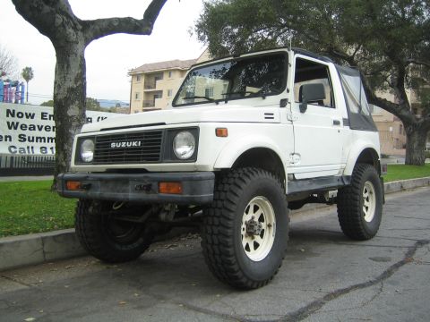
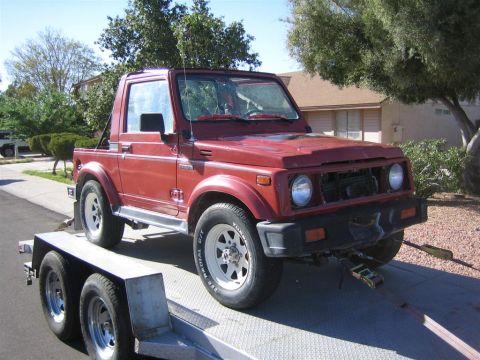
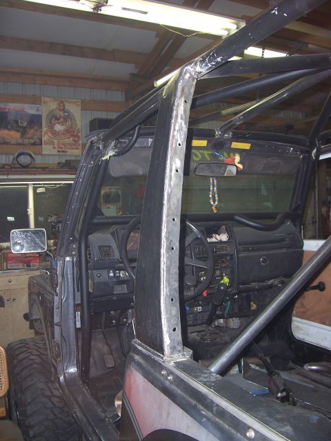
“Little Blue”/
Photo
supermotors.net/registry/media/420679
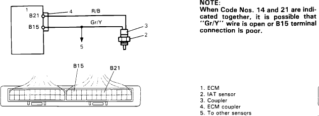
Suzuki Samurai IAT Sensor Wiring Diagram - ECM B15/B21 Terminals, Gr/Y Wire
Reference · 1986-1995 SamuraiAll 73 wiring diagrams
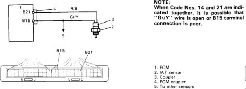
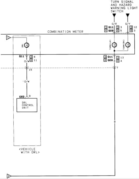
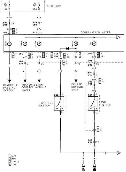
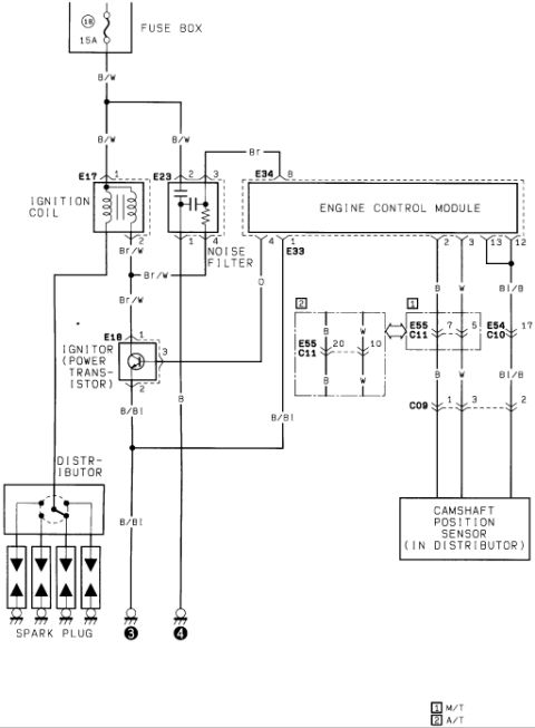

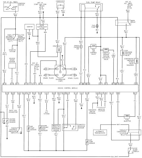
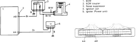

Wiring diagram showing ECM-to-IAT-sensor circuit with color-coded R/B and Gr/Y wires and a coupler terminal layout for codes 14 and 21.
Part of 1986-1995 Suzuki Samurai Wiring Diagrams
This document is a wiring diagram excerpt covering the Intake Air Temperature (IAT) sensor circuit. It shows the ECM (item 1) connected to the IAT sensor (item 2) through a coupler (item 3) via two wires: an "R/B" wire from the circuit near ECM terminal B21 and a "Gr/Y" wire from ECM terminal B15. Item 4 identifies the ECM coupler and item 5 indicates a branch going "to other sensors." A pin-grid illustration of the ECM coupler shows the physical locations of terminals B15 and B21 for probing or inspection. A troubleshooting note explains that when diagnostic Code Nos. 14 and 21 are indicated together, the likely cause is an open in the "Gr/Y" wire or a poor connection at the B15 terminal. A reader can learn the IAT sensor wire colors (R/B and Gr/Y), the relevant ECM terminals (B15 and B21), where those terminals sit on the ECM connector, and a specific diagnostic tip for interpreting simultaneous trouble codes 14 and 21. The document itself does not state a year, make, or model; it was uploaded as applying to a 1986 Suzuki Samurai.
Is this accurate? Sign in to help verify it.
Frequently asked questions
- What wire colors are used in the IAT sensor circuit?
- The diagram shows an R/B wire and a Gr/Y wire connecting the ECM to the IAT sensor through a coupler.
- Which ECM terminals connect to the IAT sensor?
- Terminals B21 and B15 on the ECM coupler, with the Gr/Y wire running from B15 to the sensor.
- What does it mean if trouble codes 14 and 21 appear together?
- Per the note, when Code Nos. 14 and 21 are indicated together, it is possible that the Gr/Y wire is open or the B15 terminal connection is poor.
- What components are identified in the diagram legend?
- 1. ECM, 2. IAT sensor, 3. Coupler, 4. ECM coupler, 5. To other sensors.

No comments yet.